
By Yangzhou Jieyao Lighting Equipment Co., Ltd. · 7 November 2026
◈ What is a tilting light pole?
A tilting light pole has a designed pivot that lets its moving section rotate into a service position. The system combines the shaft and hinge with an upright securing arrangement, a suitable lowering method and a cable route that accommodates movement. The hinge location determines which parts move and the space they need.
On an industrial platform, a light can be easy to see and difficult to reach. A tilting pole brings the light toward an accessible service position, which can reduce dependence on access equipment where the site arrangement allows it. That benefit depends on the complete installation: the moving pole must clear nearby structures, the operating equipment must remain accessible, and the lamp must arrive at a workable position.
This guide follows Jieyao’s production footage, workshop assemblies, platform-project photographs and three design drawings dated 6 November 2026. It explains the mechanisms, the manufacturing interfaces and the dimensions that matter when turning a tilting-pole concept into a serviceable installation. The pictured assemblies illustrate different configurations.
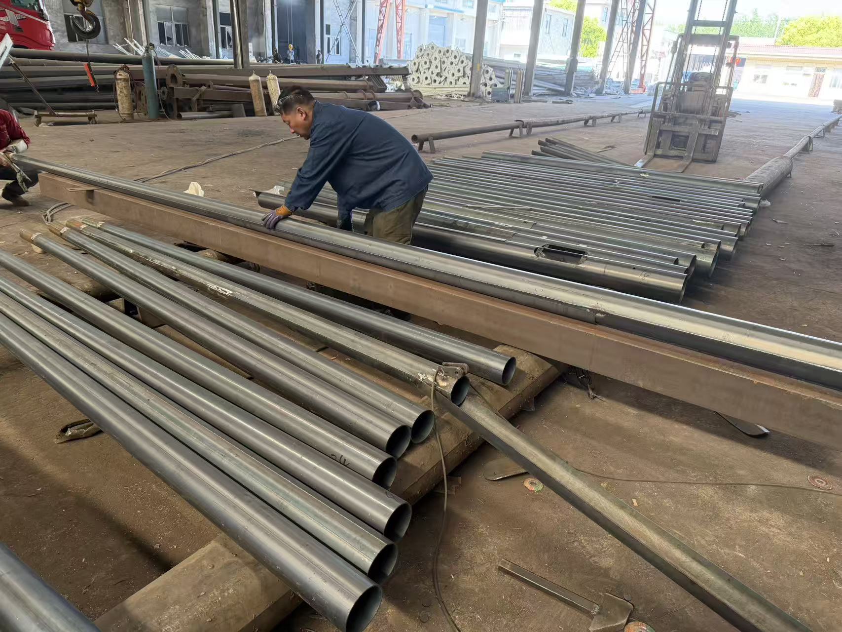
Figure 1. Pole sections arranged for workshop assembly.
The fixed part transfers loads to its support while the moving part rotates about a hinge axis. In the working position, the specified securing arrangement restrains the moving assembly. During servicing, the designated lowering system controls its movement. These functions belong to one designed assembly, even when the hinge, winch and lock are supplied as separate components.
A base-hinged pole rotates near its bottom, so much of the shaft sweeps outward. A mid-hinged pole rotates at a joint above the base; the moving member can extend to both sides of that joint. “Folding,” “tilting” and “hinged” are used across the market, so the drawing should settle the actual arrangement. Valmont’s manufacturer descriptions distinguish base-hinged and mid-hinged products rather than treating them as interchangeable. [2]
↔ Swipe horizontally for all columns.
| Design choice | What it determines | What to compare |
|---|---|---|
| Hinge location | Which portion of the pole moves | Pivot height, moving lengths and full movement envelope |
| Control method | How movement is managed | The specified winch, counterbalance, actuator or other operating arrangement |
| Working-position restraint | How the upright assembly is secured | Contact faces, fasteners or latch and their designed load path |
| Lamp / bracket interface | Where the installed equipment sits | Mass, centre of gravity, wind area and cable connection |
A hand winch is a control method; its presence does not tell you where the hinge is. Similarly, an octagonal or tapered shaft describes its form, not the lowering mechanism. This distinction prevents a purchase description from combining features that have never been checked as one assembly.
✓ Tilting pole or lowering headframe?
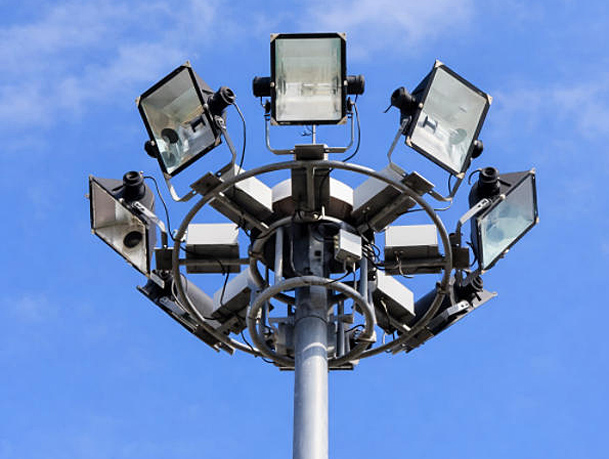
On a tilting pole, a pole section rotates. On a high-mast lowering-ring system, the mast normally remains upright while the lighting headframe travels along it. These are different maintenance arrangements, with different components and movement spaces.
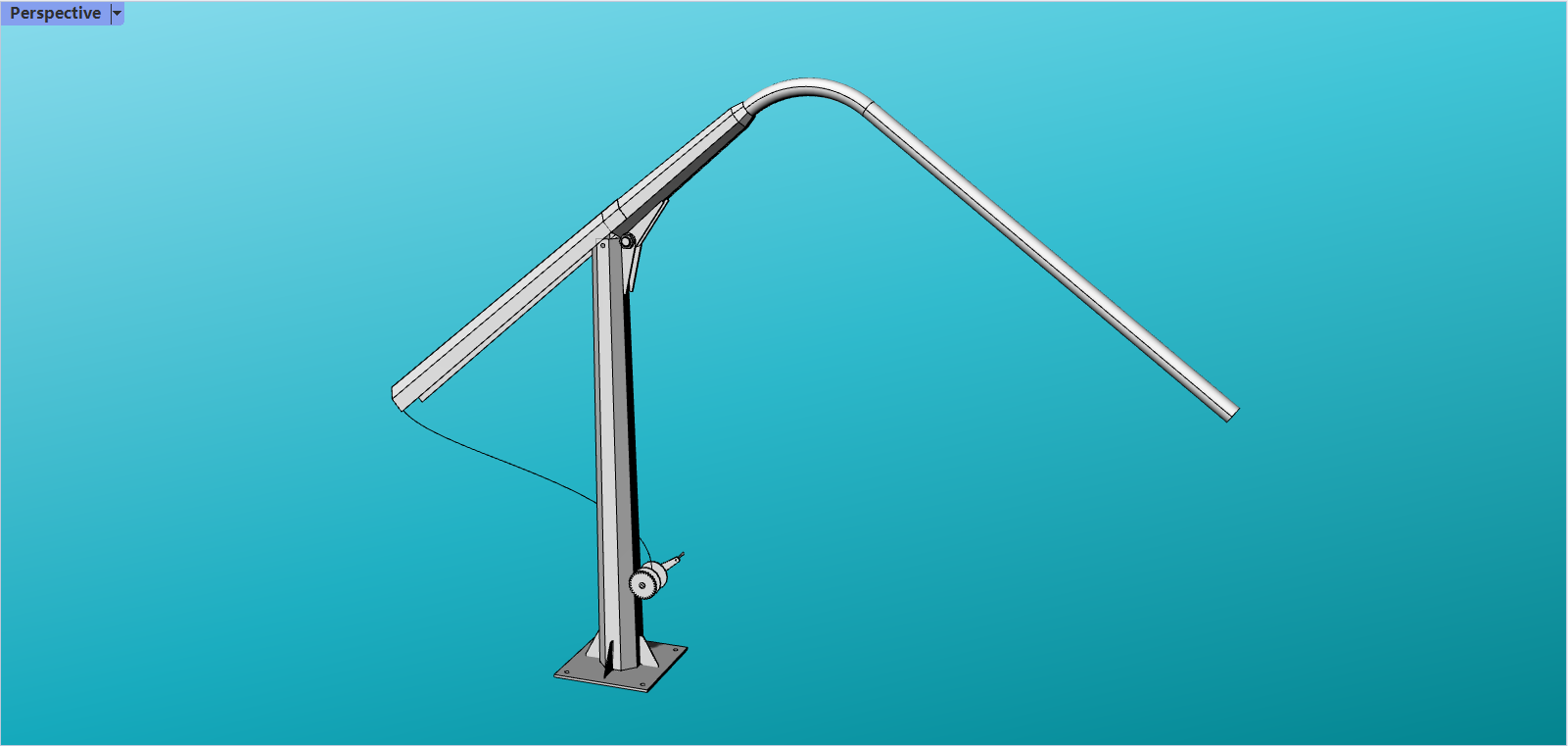
Figure 2. Winch-controlled tilting-pole design view.
The design view shows a fixed support, a pivoted upper assembly, a side-mounted winch and a line connected to the moving member. The line’s point of attachment and its angle to the moving member matter: they affect the leverage available throughout the movement. A winch selected from the pole’s total mass alone leaves out this changing geometry.
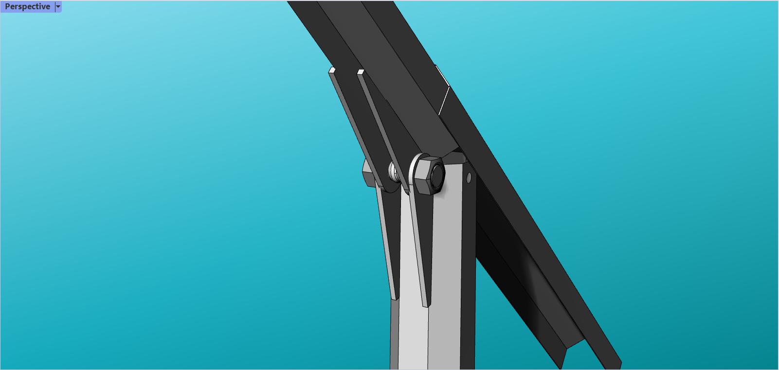
Figure 3. Pivot connection and side-plate detail.
At the hinge, check the axis, plate arrangement, bearing surfaces and pin retention. At the working-position joint, identify the surfaces and securing parts that resist the specified loads. The pivot provides rotation; the drawing must also explain restraint when the pole is upright. Our guide to hinge stops and mechanical locks develops that distinction in more detail.
For a winch-controlled arrangement, the engineering review also covers the line, attachments, drum and braking or holding provisions specified for that system. The design must address the full range of positions, not just the initial pull. Component ratings and operating limits belong to the supplied assembly documents.
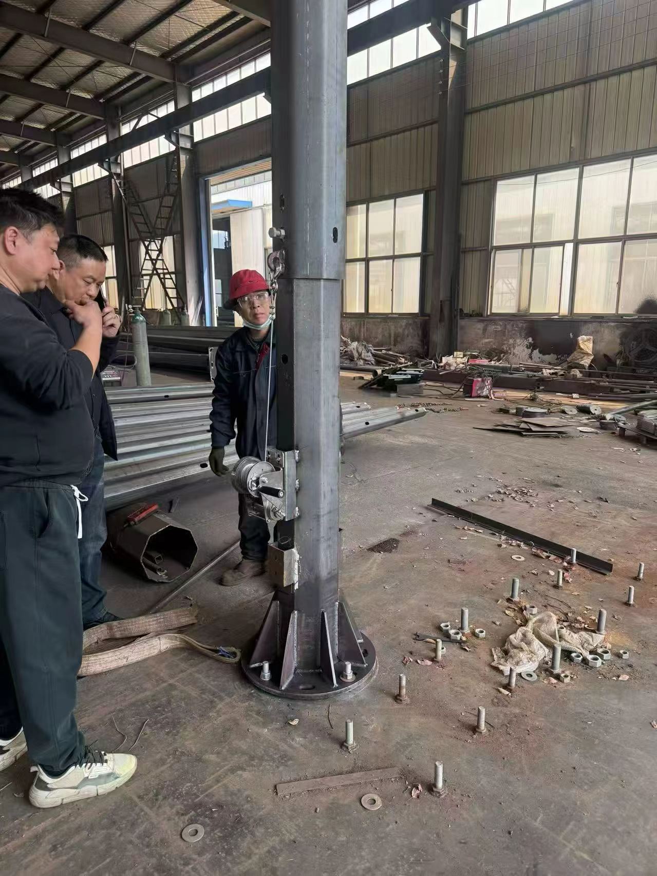
Workshop assembly with a side-mounted hand winch.
The workshop material captures details that a finished product photograph can hide: the shaft on a support bed, the hinge plates around a transverse connection, the local welding work and the relationship between the assembled sections. Those are useful manufacturing observations. Acceptance still needs records for the actual parts and configuration.
Before relying on a moving joint, the shaft sections and hinge must align with the intended axis and closing position. The workshop support bed helps present the parts for fitting and checking. A joint that rotates freely in one position can still bind elsewhere, so the full range and the final seating position both matter.
Jieyao workshop footage showing the supported shaft sections and their movement at the joint.
The production close-up shows hinge-connection fabrication on a round shaft. The visible operation helps explain where the plates meet the pole. It does not replace the specified welding procedure, dimensional checks or weld inspection. The connection drawing should identify the material and weld requirements for that part, with inspection results tied to its production record.
Hinge fitting and welding during fabrication.
Corrosion protection changes the dimensions of mating surfaces. The American Galvanizers Association notes that zinc can restrict moving parts and recommends planning clearances and assembly around galvanizing. [3] For a light-pole hinge, the useful specification is the finished fit and movement requirement, coordinated with the coating process and bearing arrangement.
This is particularly relevant to pins, close-fitting plates, securing parts and threaded interfaces. Check the assembly after the specified finish is complete, and record any permitted finishing or repair method. A smooth bare-steel fit does not settle the finished assembly’s fit.
↔ Swipe horizontally for all columns.
| Manufacturing stage | Record to retain | Why it matters |
|---|---|---|
| Shaft and hinge fit-up | Dimensions, axis alignment and closing position | Connects the manufactured geometry to the drawing |
| Connection fabrication | Material / weld requirements and inspection record | Ties local fabrication to the intended load path |
| Corrosion protection | Finish system and inspection scope | Coordinates protection with mating surfaces |
| Final assembly | Pin retention, securing parts and moving clearances | Checks the supplied assembly rather than loose parts |
| Movement acceptance | Configuration, operating range and acceptance criteria | Shows what equipment and conditions the demonstration covers |
Three Jieyao drawings dated 6 November 2026 provide a concrete design case. They share a labelled nominal mounting height and base interface, while their upper-end arrangements differ: the set includes bent-arm and top-plate configurations. Compare each luminaire connection against its own drawing rather than treating the three views as one universal specification. [1]
↔ Swipe horizontally for all columns.
| Item | Value on the drawing set | How to use it |
|---|---|---|
| Nominal mounting height | 2,500 mm | Use the stated height datum for this design case |
| Base-plate plan size | 380 × 380 mm | Coordinate support dimensions and installed orientation |
| Hole-centre pattern | 310 × 310 mm square | Compare the anchor pattern independently from plate size |
| Corner-hole diameter | Ø18 mm, typical | Check the specified fastener / anchor arrangement separately |
| Edge to corner-hole centre | 35 mm | Read with the hole-centre layout |
| Labelled cable openings | 35 mm ID, with rubber grommet | Coordinate cable protection and the electrical route |
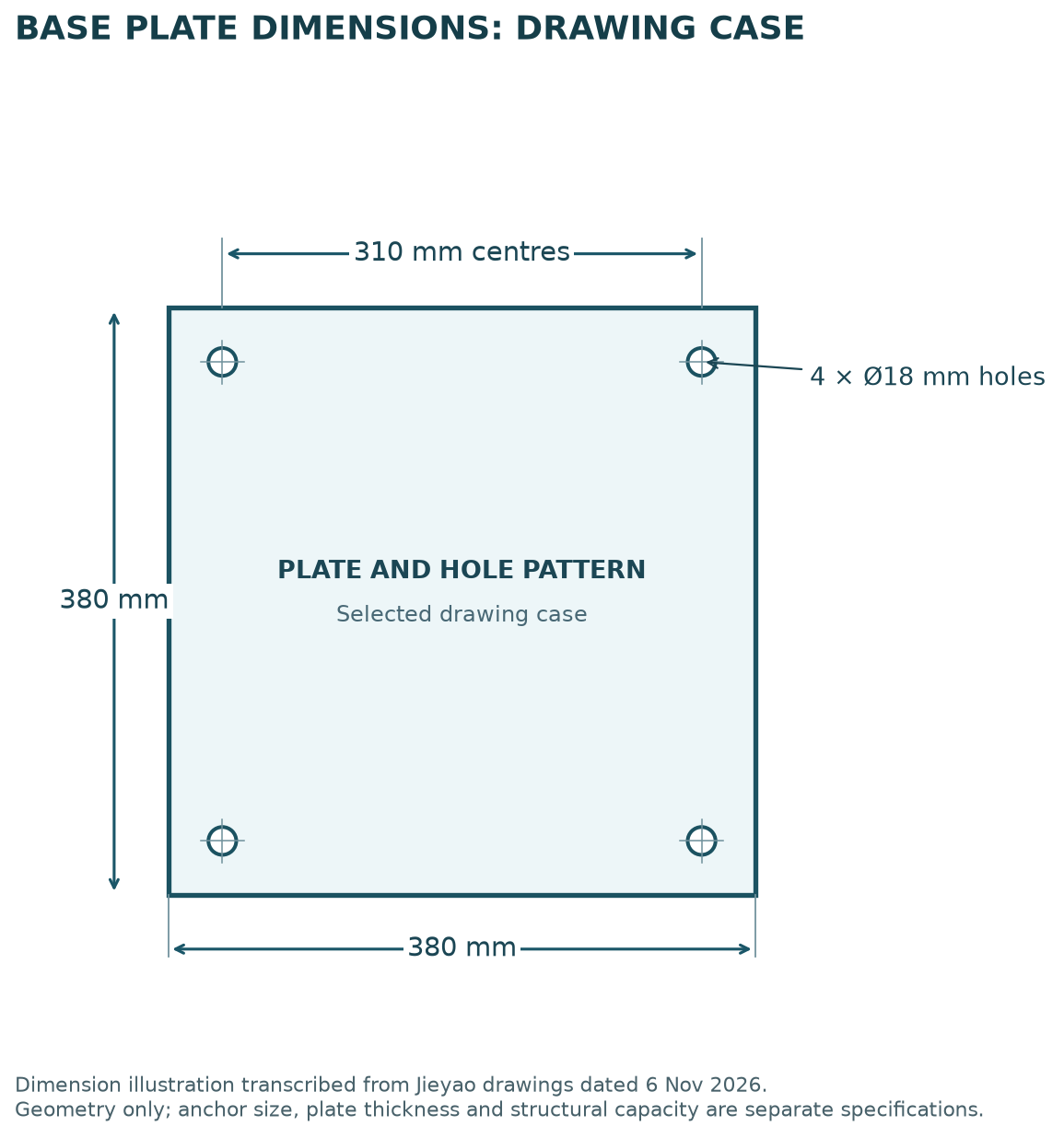
Figure 4. Base-interface dimensions transcribed from the Jieyao drawing set.
A quick geometry check makes the table easier to audit: (380 − 310) ÷ 2 = 35 mm from plate edge to hole centre. With an 18 mm circular hole, the corresponding nominal plan distance from the hole edge to that plate edge is 35 − 18 ÷ 2 = 26 mm. These calculations describe the drawn geometry; they do not establish plate strength, anchor capacity or a permissible installation tolerance.
The cable-opening diameter is a separate callout. A 35 mm opening with a grommet is not a shaft diameter, and an 18 mm hole does not by itself specify an anchor grade or its embedment. Keeping these meanings separate prevents a dimension table from becoming an accidental installation specification.
▤ A configuration-specific case
The values above belong to the illustrated 2,500 mm design case. Other pole heights, head arrangements and supports use their own coordinated drawings. Select the lamp, arm, hinge and base as a complete configuration.
Open the three CAD-exported PDF reference drawings for the illustrated 2,500 mm platform-pole case. Each sheet shows its upper-end arrangement, pivot and winch layout, base detail and cable-opening callouts. A combined three-page set is also available.
↓ Drawing 01 — bent-arm arrangement · PDF · 126 KB
↓ Drawing 02 — alternative bent-arm arrangement · PDF · 124 KB
↓ Drawing 03 — top-plate arrangement · PDF · 118 KB
↓ Complete drawing set — all three sheets · PDF · 366 KB
Drawing date: 6 November 2026. Dimensions are in millimetres. These reference drawings describe the illustrated configuration; installation and operation follow the project-specific approved documents.
At Jieyao’s factory entrance, the demonstration shows the moving shaft turning about an elevated hinge while the lower support remains upright. The upper assembly passes through inclined and near-horizontal positions. It is a useful view of the mechanism because the motion of both ends can be followed against the stationary support.
Mid-hinged pole movement outside the Jieyao workshop. The recorded configuration is a bare shaft; final assembly acceptance uses the specified installed equipment.
A lamp, bracket or additional device changes the moving assembly’s mass distribution. For a counterbalanced system, review those changes with the manufacturer. IUP’s TP-007 guidance explicitly restricts changes to the balance weights and luminaires on its own mid-hinged design, illustrating why the equipment configuration belongs in the movement review. [4]
As a simple sensitivity example, adding an assumed 5 kg lamp at 4 m from a hinge adds up to 5 × 9.81 × 4 = 196.2 N·m of gravitational moment when that lever is horizontal. This is an illustrative maximum static contribution, not the load or rating of the filmed pole. The control system must also account for the rest of the moving assembly, its geometry and the specified operating conditions.
The lamp’s final service position is only one point in the movement. The upper assembly sweeps through intermediate positions, while any moving extension behind the hinge sweeps on the opposite side. Railings, pipes and adjacent equipment can therefore obstruct a pole that appears to fit when upright.
The following independent geometry example isolates that effect. Assume a fixed hinge 3.00 m above level reference ground, an upper straight length of 4.00 m and a rear straight length of 2.00 m. The assembly is a rigid line rotating in one plane, and angle θ is measured from upright. These assumed dimensions explain the mechanism; they are separate from the 2,500 mm drawing case above.
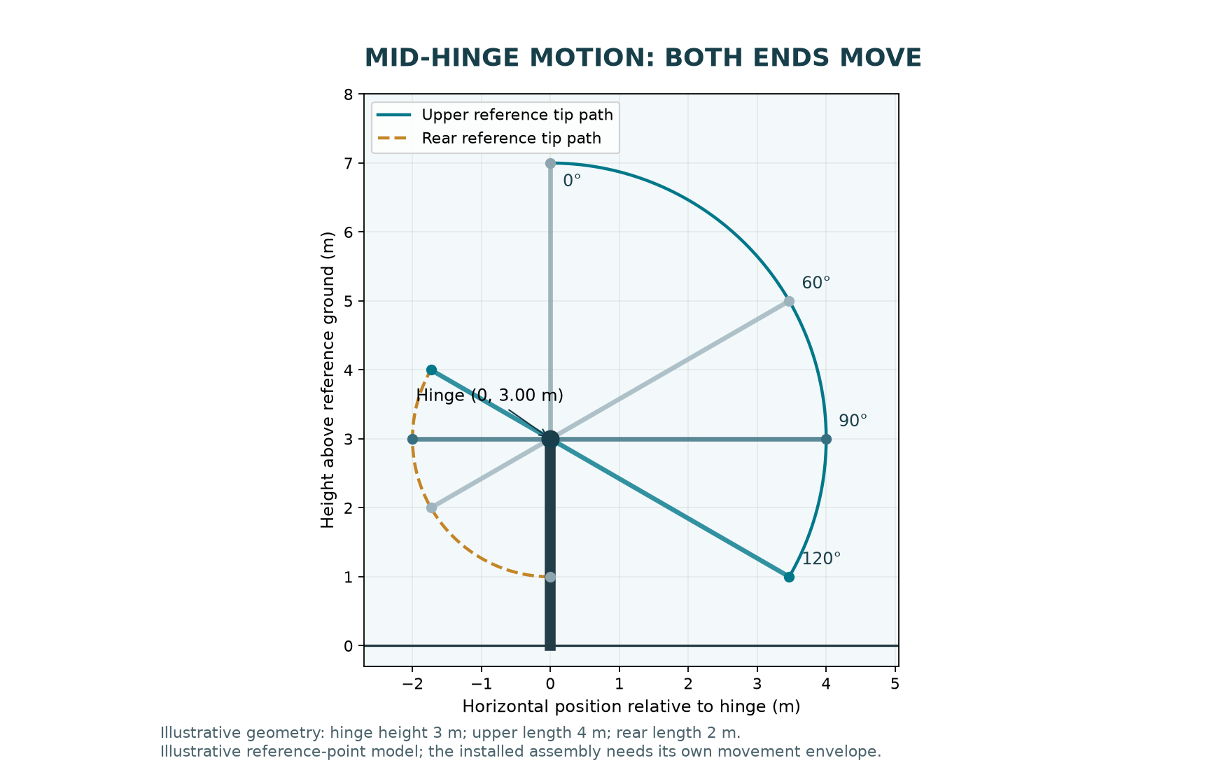
Figure 5. Original geometry analysis: the upper tip descends as the rear tip moves upward.
↔ Swipe horizontally for all columns.
| Angle from upright | Upper reach x | Upper height z | Rear reach x | Rear height z |
|---|---|---|---|---|
| 0° | 0.00 m | 7.00 m | 0.00 m | 1.00 m |
| 30° | 2.00 m | 6.46 m | −1.00 m | 1.27 m |
| 60° | 3.46 m | 5.00 m | −1.73 m | 2.00 m |
| 90° | 4.00 m | 3.00 m | −2.00 m | 3.00 m |
| 120° | 3.46 m | 1.00 m | −1.73 m | 4.00 m |
Upper coordinates are x = 4 sin θ and z = 3 + 4 cos θ. Rear coordinates are x = −2 sin θ and z = 3 − 2 cos θ. At 120°, the upper tip is 1.00 m high, but the rear tip has risen to 4.00 m. The largest upper horizontal reach in this range occurs at 90°: 4.00 m, rather than the 3.46 m reach at the final illustrated position.
✓ Check the path, then the working area
Add the actual lamp, curved arm, shaft width, cables and operating equipment to the movement envelope. Then provide the site-specific operating and exclusion area. The reference-point calculation does not supply those allowances.
For an octagonal or tapered shaft, the attachment sizes also depend on the reference section and measurement convention. Our folding-direction and clearance guide explains those interfaces. For equipment-position effects, see hinged-pole weight and moment.
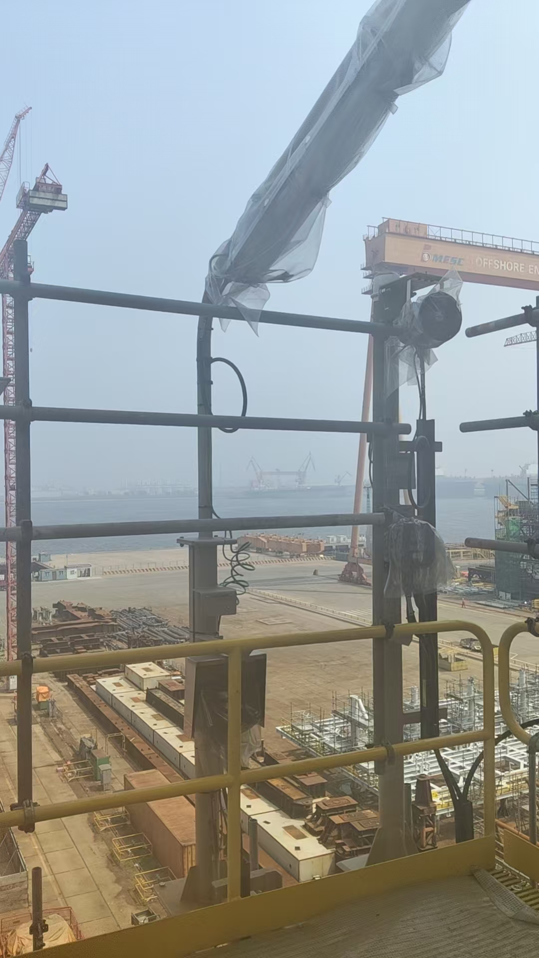
Figure 6. Tilting-pole arrangement on an elevated industrial platform.
The platform project shows the pole beside permanent steelwork, railings and cable routes. This is a different access problem from a roadside pole on an open verge. The maintenance position must be usable from the platform, with room for the operator and equipment while keeping access and escape routes workable.
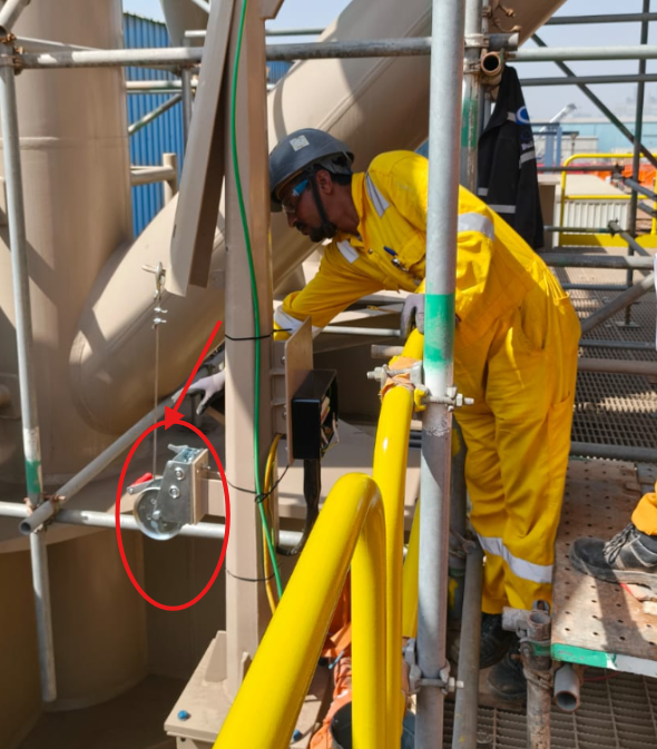
Figure 7. Side-mounted hand winch at the platform installation.
The winch position is part of that layout. Check handle access, its operating sweep and line routing against the railing and nearby equipment. A removable handle shown on a drawing still needs a usable working space when fitted. Put the operating position on the layout rather than leaving it to be discovered after installation.
The line shown beside the pole belongs to the movement-control arrangement. The electrical cable has a different duty. Its route needs enough controlled flexibility to follow the moving section without being pinched, pulled against an edge or caught by the mechanism. Identification of those separate routes should remain clear in the assembly drawings and maintenance documents.
For a shipyard or coastal platform, specify corrosion protection for the shaft, hinge, fasteners and operating equipment as coordinated interfaces. The finish on the large shaft does not establish the protection of a pin or winch. Our marine pole coating guide explains how to read a layer schedule and its inspection evidence.
Treat installation as the placement of a moving system. The support orientation determines the hinge direction; the arm geometry determines the lamp’s path; and the control arrangement determines where the operator stands. These relationships should be resolved before the base is fixed in position.
↔ Swipe horizontally for all columns.
| Project stage | Information to coordinate | Handover evidence |
|---|---|---|
| Before installation | Support / foundation design, anchor pattern, orientation, cable entry and complete equipment schedule | Approved configuration and interface drawings |
| Before movement acceptance | Installed masses and positions, full movement range, securing arrangement and operating limits | Manufacturer procedure and agreed acceptance plan |
| At commissioning | As-built geometry, electrical protection, cable movement and accessible maintenance position | Recorded checks for the supplied configuration |
| During service | Inspection intervals, component condition and proposed equipment changes | Maintenance history and manufacturer review of changes |
The operating procedure should identify isolation, movement control, securing and inspection requirements for the supplied mechanism. A short factory video is an explanation of visible movement; the project’s controlled instructions govern the installed assembly. Set operating weather limits and the required competent personnel through those documents.
Changes after handover deserve the same attention. Replacing a lamp, adding a camera, moving a bracket or altering a cable loop can affect motion or loads even if the pole height remains unchanged. Retain a clear equipment schedule so the maintenance team can identify the original configuration.
A tilting design is worth comparing where servicing height or access equipment creates a recurring difficulty and a suitable movement area can be provided. Elevated platforms, constrained industrial areas and some pathways can benefit from bringing equipment toward an accessible location. The actual site still decides whether that movement is practical.
A fixed pole may be simpler where access equipment can reach it conveniently and the site cannot accommodate a swing envelope. A lowering headframe may suit another high-mast application. Compare the maintenance method with the pole layout and lighting task; the number of moving components alone does not determine the best option.
For a Jieyao inquiry, provide the mounting height and support arrangement; lamp and bracket geometry; installed masses and projected areas; desired service direction; nearby obstacles; exposure conditions; and the required maintenance position. Jieyao can use that brief to discuss a coordinated configuration rather than selecting a hinge from height alone. Explore our folding street lighting pole configurations or send the project layout to Jieyao Lighting.
Yes, where the support and complete movement arrangement are designed for that platform. Check the equipment path, operator position, handle access and cable routing against the surrounding steelwork. The project photographs above illustrate why those interfaces matter.
A winch controls movement in its designed arrangement. The upright securing function must be identified separately on the assembly drawing. Do not infer that the winch or an access padlock provides structural restraint solely from its appearance.
Shaft shape alone cannot decide that. Compare the structural design, hinge connection, attachments, finish and movement requirements for the complete configuration. A nominal diameter or across-flats size is only one input.
Review its mass, centre of gravity, wind area, fixing and cable arrangement before substitution. A mid-hinged or counterbalanced assembly can respond differently even when the replacement lamp has a similar wattage.
They describe the selected platform-pole design case. Other mounting heights and equipment arrangements need their own coordinated dimensions, operating equipment and support design.
[1] Jieyao project and production records. Three single-sheet platform-pole drawings dated 6 November 2026 (available in the CAD drawing downloads above); associated CAD views; workshop fabrication and movement footage; and platform-project photographs. Figure 4 transcribes selected base-interface dimensions. The movement chart in Figure 5 uses its own stated assumptions. No rated-load test result is inferred from the footage.
[2] Valmont Structures, Functional Hinged Poles. Manufacturer reference for the distinction between base-hinged and mid-hinged arrangements.
Valmont — Functional Hinged Poles
https://www.valmont.ma/produits-et-solutions/eclairage/fonctionnels-basculants/summary
[3] American Galvanizers Association, Moving Parts. Guidance on moving-part clearances and assembly around galvanizing; the pole’s specific fit follows its design.
American Galvanizers Association — Moving Parts
https://galvanizeit.org/design-and-fabrication/fabrication-considerations/moving-parts1
[4] International Utility Poles, TP-007 Mid-Hinged Pole Operation Guide. Manufacturer-specific reference on changes to counterbalance weights and installed luminaires.
IUP — TP-007 Mid-Hinged Pole Operation Guide
https://www.iupoles.com/doc/tp007-mid-hinged-pole/
Contact Us
Get a custom lighting solution and quotation for your project. Yangzhou Jieyao Lighting Equipment Co., Ltd. manufactures outdoor lighting and steel poles in Guoji Town Industrial Park, Gaoyou City, Yangzhou, Jiangsu, China. The company reports a 10,000 m² factory site, more than 60 employees including more than 10 technical personnel, and more than 100 production and testing machines. The present company name dates from 2017; Jieyao Poles’ published history traces the team’s manufacturing lineage to 2006. The stated 15 years of experience refers to the team. The company reports exports to more than 60 countries. Do you have any questions or requests?
Email: jay@jieyaolighting.com

Click to Chat.
Im online now.
 English
 Español
 Bahasa Indonesia