
◈ What defines a folding light pole’s required space?
The hinge position, moving length, folding direction and attached equipment define the movement envelope. Octagonal or tapered describes shaft geometry; it does not specify the hinge type or space needed to lower the pole.
A folding pole can fit its foundation and still be unsuitable for the servicing space. Check the upright position, the whole movement and the final service position. A fence, parked vehicle or cabinet may clear the base while obstructing the moving shaft or luminaire.
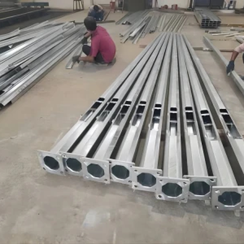
Octagonal steel pole sections and base interfaces.
A base-hinged pole rotates near its base. A mid-hinged design divides the shaft into fixed and moving portions and may use a counterbalanced arrangement. Their operating spaces and equipment can differ. Valmont’s hinged-pole range includes both types with model-specific arrangements. [1]
“Octagonal folding pole” does not resolve that difference. Show the hinge axis and moving assembly on the project drawing. A compact-folding claim for a specific mid-hinged product should not be transferred to a base-hinged design.
Ideal base-hinge example: the hinge axis is 0.70 m above level ground and the moving straight length is 7.30 m. Its upright reference tip is 8.00 m high. Ignore the lamp, bracket, shaft width and operating equipment for this first calculation. Angle θ is measured from upright.
▤ Reference-point geometry
Horizontal reach x = 7.30 sin θ.
Reference-tip height z = 0.70 + 7.30 cos θ.
Lengths are in metres. These equations describe an ideal rigid segment, not an approved site clearance.
↔ Swipe horizontally to read all columns.
| Angle from upright | Horizontal reach x | Reference-tip height z |
|---|---|---|
| 0° | 0.00 m | 8.00 m |
| 30° | 3.65 m | 7.02 m |
| 60° | 6.32 m | 4.35 m |
| 90° | 7.30 m | 0.70 m |
At 60°, the reference tip is already 6.32 m from the hinge’s vertical line while remaining 4.35 m above ground. At 90°, its reach is 7.30 m and height is 0.70 m. Checking only the final footprint would miss obstacles intersected during movement.
An arm or luminaire adds points with different offsets from the shaft centreline. Track those points through the same rotation using their actual positions. Add the shaft cross-section and equipment to form the physical envelope, then establish the required operating and exclusion area through the approved method.
↔ Swipe horizontally to read all columns.
| Constraint | What to show on the plan | Interface consequence |
|---|---|---|
| Road and traffic | Carriageway, parking and agreed work zone | Coordinate service direction with traffic control |
| Fence or building | Boundaries and projections | Check the full swing, not only the base |
| Cabinet and cables | Equipment positions and cable route | Coordinate movement and access |
| Foundation orientation | Bolt pattern and direction reference | Relate hinge axis to installed base orientation |
Use a direction arrow referenced to the site plan. Describe both hinge-axis orientation and the direction in which the moving assembly travels. “Fold left” is ambiguous without a viewpoint. Include the access opening and operating-equipment connection orientation so the assembly can be used from the intended work area.
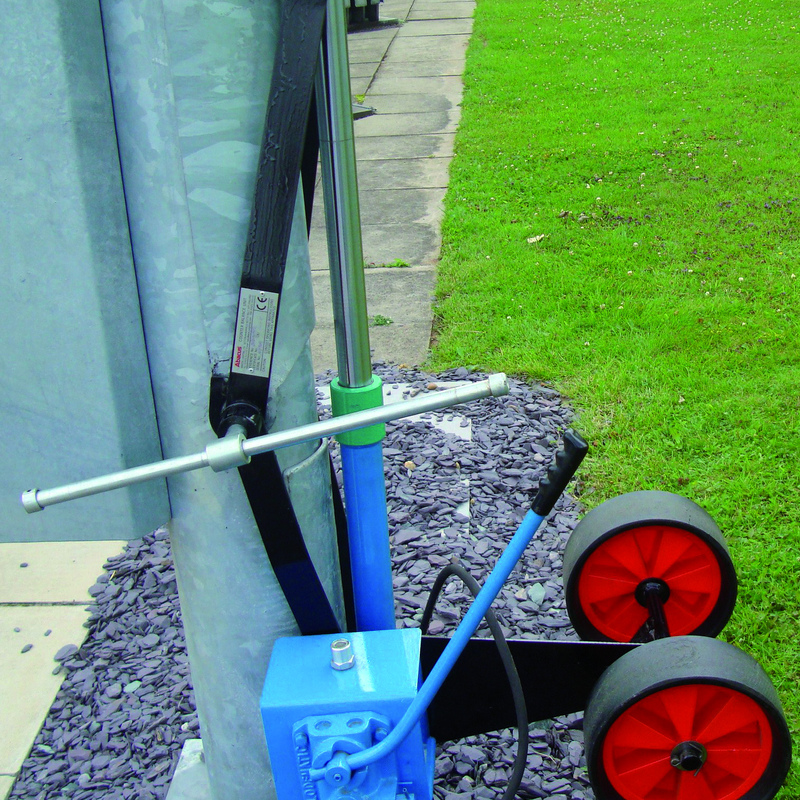
Lowering equipment and the pole connection interface.
For a regular octagon, across-corners size is larger than across-flats size. If F is across flats, across corners C = F ÷ cos(22.5°), approximately 1.0824 F. An illustrative 200 mm across-flats section is about 216.5 mm across corners. This is external regular-octagon geometry; fabrication tolerances and rounded corners require the actual drawing.
A tapered shaft changes size along its length. State the measurement height or reference section when specifying an attachment. A nominal bottom size does not establish width at a higher hinge or bracket. Wall thickness, plate arrangement and connection details remain separate design inputs.
A cable long enough upright may become tight, pinched or abraded during folding. Review the route, bend allowance, restraints and isolation through the movement. A service loop should follow the designed detail rather than find its own path inside the joint.
Before accepting a layout, compare the approved drawing with the surveyed site and operating method. Retain the envelope and direction reference with the as-built records. Later changes to cabinets, fences or luminaires can affect available space.
A folding system needs a designed moving connection, restraint, load path and operating arrangement. Shaft shape alone does not establish compatibility with a hinge or existing foundation.
Discuss your project with Jieyao Lighting
Send Jieyao Lighting the site plan, desired service direction, pole height and attached equipment geometry. Include base orientation and cable entry information when discussing an octagonal or tapered folding pole. Explore street lighting pole options or use the website contact form to share the project requirements.
1. Valmont functional hinged poles — Product descriptions distinguish base-hinged and mid-hinged arrangements. Model-specific claims are not general clearance rules.
https://www.valmont.ma/produits-et-solutions/eclairage/fonctionnels-basculants/summary
The numerical examples are original calculations by Jieyao Lighting using the stated assumptions. They illustrate a comparison method and are not measured results for a supplied product.
Contact Us
Get a custom lighting solution and quotation for your project. Yangzhou Jieyao Lighting Equipment Co., Ltd. manufactures outdoor lighting and steel poles in Guoji Town Industrial Park, Gaoyou City, Yangzhou, Jiangsu, China. The company reports a 10,000 m² factory site, more than 60 employees including more than 10 technical personnel, and more than 100 production and testing machines. The present company name dates from 2017; Jieyao Poles’ published history traces the team’s manufacturing lineage to 2006. The stated 15 years of experience refers to the team. The company reports exports to more than 60 countries. Do you have any questions or requests?
Email: jay@jieyaolighting.com

Click to Chat.
Im online now.
 English
 Español
 Bahasa Indonesia