

 English
 Español
 Bahasa Indonesia

- Product details
-
JIEYAO · PROJECT-CONFIGURED STEEL POLES
Folding & Tilting Light Poles for Ground-Level Maintenance
Choose the hinge position, lowering direction and operating arrangement around the equipment you need to service. Jieyao’s project materials show mid-hinged pole movement, a workshop hand-winch arrangement and compact platform-lighting designs with alternative top connections.
Define the pole, hinge, upright restraint, operating equipment and mounting interface as one coordinated supply package.
Request a Folding-Pole ConfigurationSend your site layout, equipment weight and wind area, mounting height and preferred service direction.
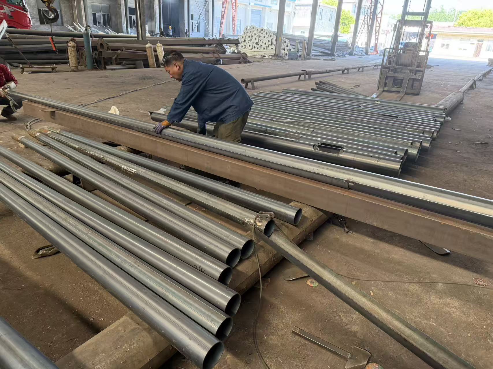
Steel pole sections during workshop assembly.
Product familyFolding / tilting steel polesConfigurationProject drawing and equipment scheduleDocumented compact case2.5 m · three top arrangementsAvailable evidenceCAD, workshop footage and site photosPRODUCT SELECTION
Choose the pole arrangement before the height
Choose an intermediate-hinge shaft for a planned lowering position, a side-mounted winch arrangement for assisted movement, or a platform configuration for restricted service access. Match the head connection and dimensions to your equipment and site layout.
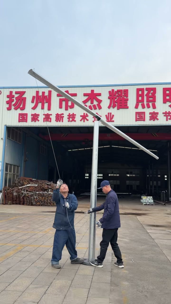
Mid-hinged shaft · frame from the factory movement video.
Mid-hinged shaft
An intermediate pivot allows the upper shaft to rotate while the lower shaft remains fixed. The factory footage below shows the joint moving on a bare pole. Choose the pivot elevation and lowering side around the location of the luminaire and the space beside the column.
- Review the upper-section length and service position.
- Define the upright restraint and access to it.
- Coordinate cables across the moving joint.
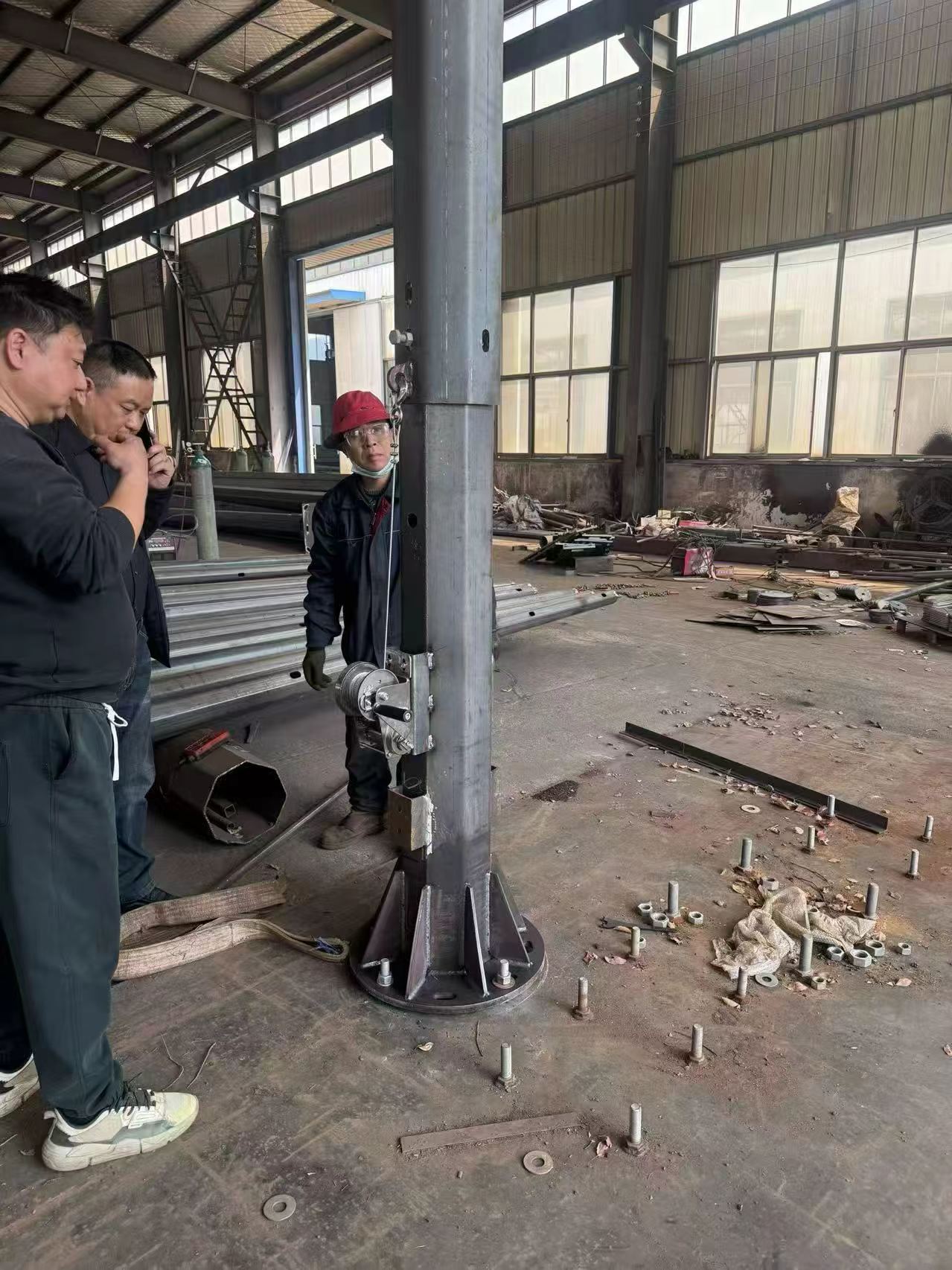
Hand-winch-assisted assembly · workshop product photograph.
Hand-winch-assisted assembly
The workshop product photograph shows an operating winch attached to the side of a flanged pole. A site photograph also shows a winch on an industrial platform. These examples make the operating station and its access part of the product selection.
- Identify the matched winch and its mounting.
- Show cable anchorage and routing.
- Keep the handle area accessible after installation.
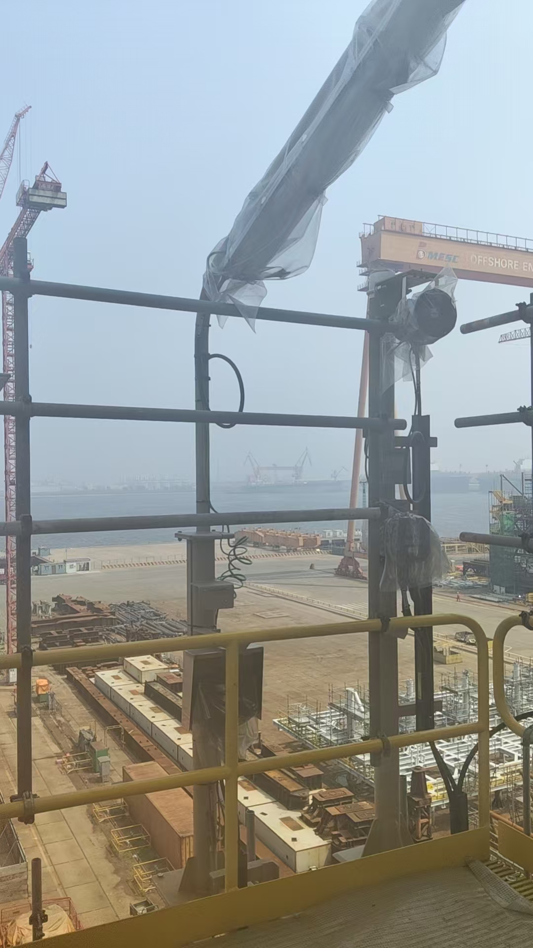
Industrial-platform installation.
Industrial-platform arrangement
The installed pole photograph shows an elevated platform arrangement with surrounding equipment and cable routing. Use this installation form when the service position must fit a restricted deck. Select the top connection and base interface against the actual structure.
- Platform layout and equipment mounting position.
- Available lowering space beside the deck.
- Winch access, handrails and cable movement.
Specify the complete lowering arrangement
A folding light pole brings its upper section towards a planned service position through a pivoting connection. The fixed lower section, moving upper section and fitted lighting equipment must be coordinated with that movement. This is particularly relevant where normal lift access is restricted or where an industrial platform offers only a narrow maintenance area.
Start with the actual service task: the equipment to reach, the surface where work will take place and the space available throughout the movement. The useful product is a matched assembly, with its hinge geometry, upright locking arrangement, cable route and operating method defined together.
Configuration direction Visible or documented arrangement Procurement choice Mid-hinged pole Upper section pivots at an intermediate shaft connection. Hinge elevation, lowering direction, head arrangement and upright restraint. Winch-assisted arrangement Separate workshop and site images show a side-mounted hand winch and cable routing. Matched operating equipment, mounting location and operating access. Compact platform design Three drawing cases show a 2.5 m nominal mounting height with different top connections. Top interface, platform envelope, base connection and maintenance position. These are different configuration examples. Select the complete assembly for the project rather than combining parts from separate photographs.
TOP CONNECTION CHOICES
Top-connection alternatives in the 2.5 m drawing set
The 01, 02 and 03 references identify drawing alternatives for the compact design. The CAD overview below explains a curved-top arrangement. Use the chosen drawing reference with your equipment outline when enquiring.
Drawing reference Top arrangement Selection details 01 Long curved top Lateral light position, full lowering envelope and equipment mounting interface. 02 Short curved top 600 mm horizontal dimension shown on this drawing; check against the required equipment position. 03 Top-plate connection Equipment footprint, fixing pattern and mounting orientation. 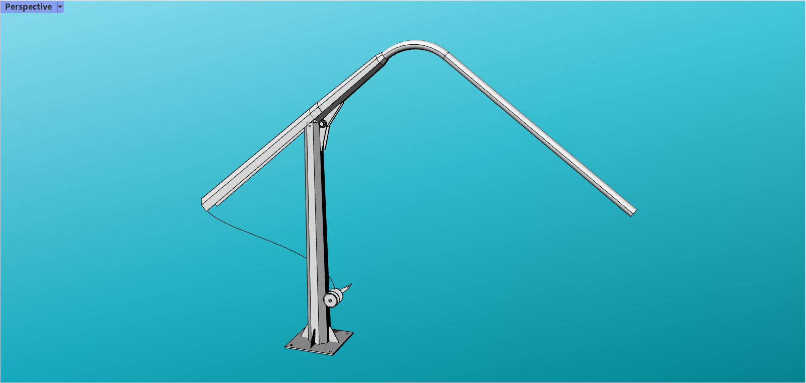
CAD configuration view: curved upper member, pivot, fixed shaft and operating arrangement.
Choosing between the three: compare the required light position, equipment connection and available lowering space. The 2.5 m reference dimensions belong to this drawing set; taller poles require a separate schedule.See the hinge and pole movement
Bare-pole hinge movement at the Jieyao factory entrance.
Pole-section movement on workshop supports.
The clips show how the bare pole sections move around their joints. The operating arrangement for a delivered assembly also needs to account for the fitted luminaires, brackets and cables. The demonstration clips do not establish a rated top load or an operating-force limit.
Hinge connection, restraint and cable interfaces
The hinge provides the pivot; the upright restraint secures the serviceable assembly in its normal position. Specify their connection details together with the pole sections and equipment attachment. For an assisted design, include the intended cable route and operating mechanism in the same drawing set.
The supplied CAD view shows the relationship between the moving member, side plates and pivot. It is useful for discussing the connection geometry. The shaft and hinge dimensions for manufacture belong on the drawing of the selected configuration.
For a focused explanation of the separate mechanical functions, see hinged-pole stops and mechanical locks.
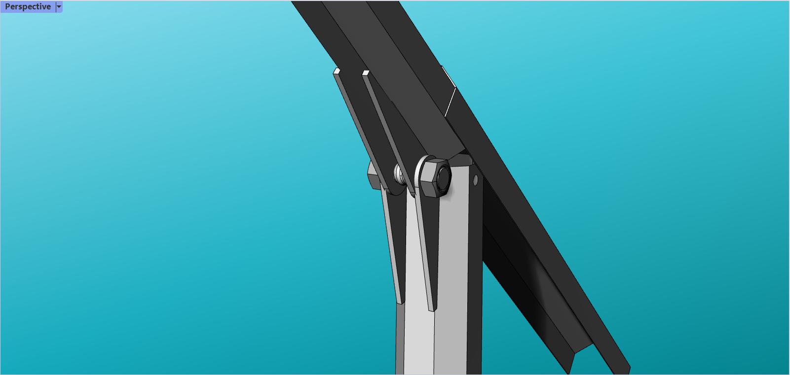
CAD view of the pivot and side-plate arrangement.
Drawing reference: a 2.5 m platform-lighting design
Three Jieyao drawings dated 6 November 2026 illustrate a compact tilting-pole design with alternative upper connections: a longer curved arm, a shorter curved arm and a top-plate connection. Each sheet labels the nominal mounting height as 2500 mm. This design case is separate from the taller workshop pole and other folding-pole options.
Drawing detail Dimension in this design case Meaning for the connection Nominal mounting height 2500 mm Mounting-height label on drawings 01, 02 and 03. Square base plate 380 × 380 mm Outside plate plan dimensions. Fixing-hole centres 310 × 310 mm square pattern Hole-centre spacing, not a bolt-circle diameter. Corner fixing holes Ø18 mm, typical Hole diameter, not a specified anchor-bolt grade or capacity. Edge to hole centre 35 mm Edge distance shown in the base plan. Cable opening 35 mm internal diameter with rubber grommet Cable passage, not pole diameter. The base plan establishes an interface for this example; it does not size a platform structure, concrete foundation or anchor system. The project designer needs the selected pole reactions and supporting-structure information to approve those connections.
Drawing selection: identify the chosen top connection as well as the mounting height. A different arm or luminaire changes the complete assembly even when the base plate looks the same.
STRUCTURAL DETAILS
What belongs in the finished assembly
Upper and lower members
The fixed lower member carries the pivot connection. The upper member carries the head arrangement and moves during servicing. Specify their section sizes, lengths and connection positions on the order drawing so the delivered parts form the intended assembly.
Pivot and side plates
The pivot position controls the motion. Plate spacing, pin fit and adjacent clearances affect assembly and rotation. Include these details with the connection drawing and agree the inspection points for the selected design.
Upright restraint
Identify how the upper member is retained in the normal position and how that restraint is accessed. The operating cable and the upright restraint perform different tasks; both belong in the product scope.
Equipment connection
Show the lantern, bracket or top plate as supplied. Equipment mass and its offset from the pivot affect the configuration review. Include any additional attachment instead of treating it as a later site addition.
Cable and entry detail
Define the cable entry, protected passage and movement allowance at the joint. The compact drawing set identifies an internal cable opening with a rubber grommet. Keep electrical routing clear of contact and pinch areas throughout the intended movement.
Base and supporting structure
Match the base plate to the foundation or platform connection. For a deck installation, provide the supporting member layout and fixing access. Confirm which party supplies anchors, fasteners and connection design.
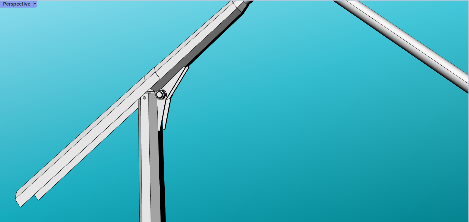
CAD detail of the pivot and rear connection geometry.
Hinge fabrication and workshop fit-up
Workshop welding and fitting of a hinged connection.
The production footage shows a small hinge connection being positioned, welded and handled on a pole section. The separate movement footage shows the assembled connection rotating. Together they provide a practical view of fabrication and fit-up, without substituting for the agreed inspection of a finished order.
For procurement, define the material schedule, hinge and lock fit, surface protection, access openings, wiring protection and representative assembly checks with the order. Agree the condition in which the pole is supplied—bare assembly or fitted equipment—and identify the components used during any specified functional check.
MANUFACTURING AND ORDER CHECKS
From the selected drawing to a coordinated pole package
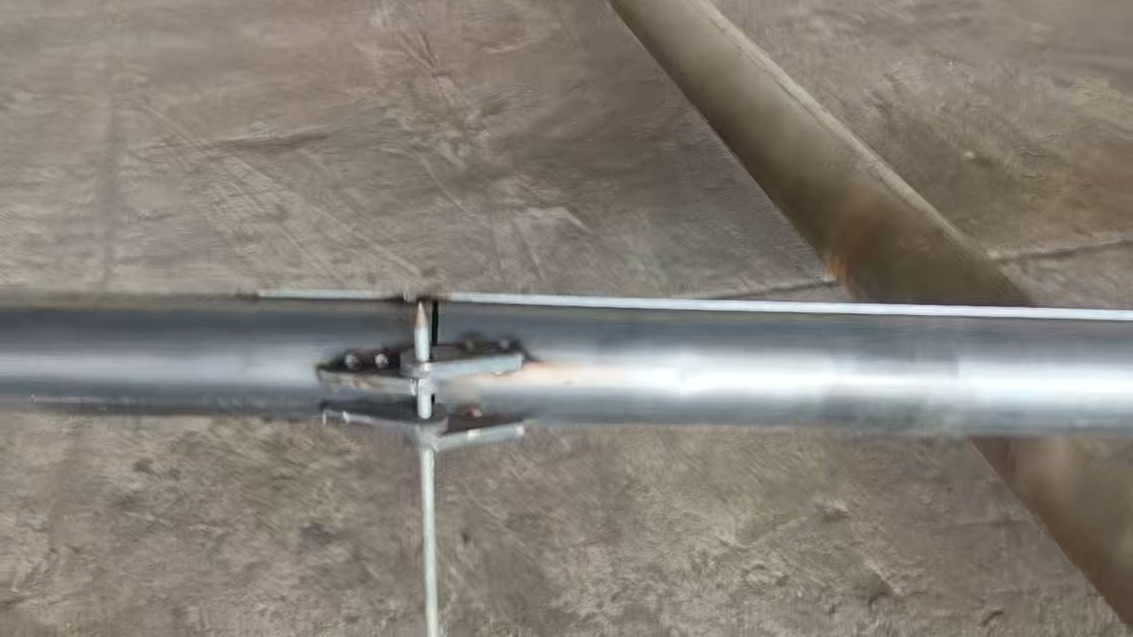
Hinge and pole-section fit-up in the workshop.
Fabrication follows the selected arrangement
The workshop photographs and videos show steel pole handling, hinge fit-up and movement of assembled sections. Use the order drawing to connect these activities to the required shaft, hinge and base geometry. The selected finish and delivery state should be written into the same scope.
A useful inspection schedule identifies what will be measured and what will be demonstrated. Agree the assembly condition for the functional check, including whether the nominated light and operating equipment are fitted. Request the records relevant to that configuration.
01 · DRAWINGFreeze the geometry
Confirm height, head connection, hinge location, base pattern and lowering direction against the site layout.
02 · MATERIALSIdentify the steelwork
Put material grades, wall thicknesses, plates, pins and specified fasteners on the approved schedule.
03 · FIT-UPCheck the interfaces
Review hinge alignment, restraint engagement, equipment connections and cable passages on the assembly.
04 · FINISHDefine surface protection
Specify the coating system and any colour requirement for the stated environment. Agree measurable acceptance criteria.
05 · FUNCTIONAgree a representative check
Define the fitted condition, operating arrangement and required movement or locking demonstration in the inspection plan.
06 · DISPATCHMatch parts and documents
List the supplied sections, accessories, assembly information and identification needed at the installation site.
Project context: an elevated industrial platform
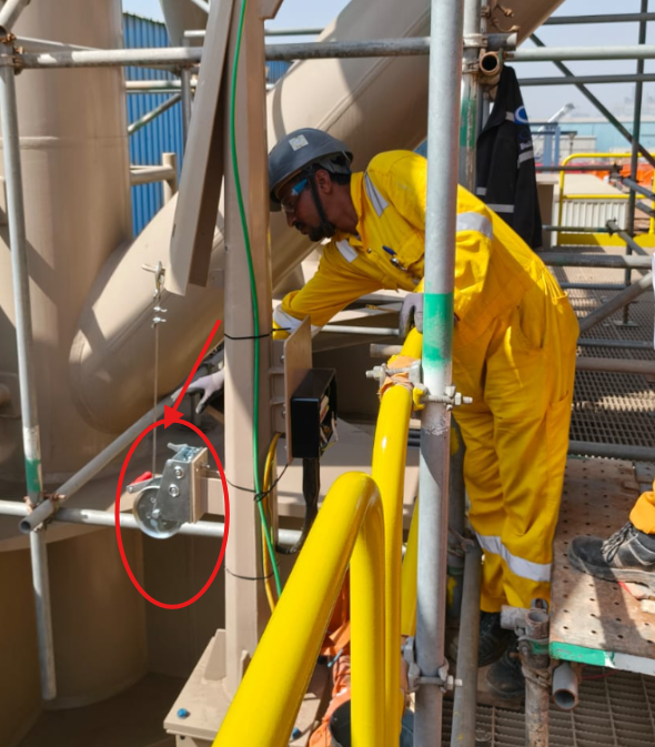
Installed operating equipment beside the platform handrail.
The project photograph shows why maintenance access needs to be considered beside the pole geometry. Guardrails, deck edges, structures, cable loops and the position of the equipment all influence the usable service area. A folding direction that works on an open yard may be unsuitable on a narrow platform.
Provide an elevation or section through the platform, not only a pole centre mark on a plan. Show the intended movement envelope, landing or working position, pedestrian access and any nearby equipment. Describe corrosive exposure and the required finish with the project specification.
The photograph is a project-context example, not the dimensional definition of the 2.5 m drawing case. See the folding-direction and clearance guide for the inputs that help coordinate a layout.
The separate site detail shows the operating equipment beside a narrow working area. This is a useful selection check: an accessible pole base does not automatically provide enough space for the operator, the handle movement or the lowered head.
For a similar location, mark the operator station, handrail, deck openings and access route on the layout. Include the direction of lowering and the work position of the luminaire. These inputs allow the pole arrangement to be reviewed alongside the structure around it.
Specify the required electrical isolation and maintenance procedure with the site team. Pole supply, supporting-structure design, installation and site operation need clear responsibility in the purchase scope.
HEIGHT AND HEAD CONFIGURATION
Compact platform designs and taller pole enquiries
Start with the required mounting height, then select the head arrangement and service position. The documented compact design and the taller directions in the product archive have different engineering inputs. A 10 m or 12 m enquiry needs its own shaft and connection schedule.
Selection direction Starting information What to define next 2.5 m compact platform case Three supplied drawings with curved-top or top-plate alternatives. Selected top connection, platform interface and equipment outline. 6 m hinged-pole enquiry A separate archived drawing exists. Current released material and dimension schedule; do not use the compact-case values. 10 m / 12 m project enquiry Taller pole and head-configuration directions in the product archive. Required height, lantern or floodlight layout, total equipment data and site criteria. Single- or double-arm direction One-sided reach or two-sided lighting layout. Arm length, orientation, attachment method and the complete moving-head geometry. Top-mounted or floodlight bracket direction Equipment positioned above the shaft or on a mounting bracket. Exact attachment dimensions, weight, centre of gravity and projected wind area. For any height, submit the actual equipment data with the bracket arrangement. Wattage describes the electrical load; it does not describe the mechanical effect of the mounted assembly. The weight-versus-moment guide explains the purchasing inputs.
Define the quotation package
Supply item Define in the quotation Buyer or site input Pole and pivot assembly Shaft sections, hinge, upright restraint and top connection. Height, equipment layout, design criteria and service direction. Operating equipment Selected assist mechanism, cable arrangement and operating accessories. Operator access and available working area. Base and fixing interface Plate drawing, hole pattern and included fixing components. Platform or foundation information and connection-design responsibility. Lighting and electrical package Luminaires, brackets, cables and terminals included or supplied by others. Exact equipment models, weights, wind areas and electrical requirements. Finish and delivery Surface protection, color, packing, documents and dispatch scope. Exposure, quantity, destination and inspection requirements. Send the site plan, a side elevation, equipment schedule and quantity with your enquiry. Jieyao can then review a defined folding-pole package rather than quote an unqualified height-only description.
Send Your Drawings and Pole ScheduleFolding and tilting pole questions
Are folding, tilting and hinged light poles separate product families?
The terms can describe overlapping lowering arrangements. Identify the hinge position, shaft configuration and operating method in the enquiry so the quoted assembly is unambiguous.
Can an existing luminaire be retained?
Provide its mounting details, mass, centre of gravity, projected wind area and cable requirements. Compatibility depends on the complete assembly, not lamp wattage alone.
Does the pole always eliminate a lift or access platform?
No universal access claim is made. The service position, available workspace, isolation method and site procedure determine how maintenance can be carried out.
Can a different winch be fitted later?
Treat a change of operating equipment as a configuration change. Check its mounting, force path, cable arrangement and operating instructions with the responsible supplier before substitution.
Can a platform drawing be used for a ground-mounted pole?
The supporting connection and available service space differ. Send the foundation or platform details for the actual installation. The reference base dimensions do not replace connection design for a different structure.
What should I send for a replacement pole?
Send photographs of the existing installation, its drawing if available, mounting height, fixing pattern and the exact equipment to retain. Identify the available lowering direction and any changes to the surrounding area.
Which documents should be included in a purchase order?
List the selected assembly drawing, material and finish requirements, supplied operating equipment, inspection records and assembly information. Agree any additional testing or project-specific documentation before ordering.
-
-