
◈ Do a hinge, travel stop and mechanical lock do the same job?
A hinge defines the rotation axis. A travel stop limits movement. The designed securing arrangement holds the pole in its working configuration. Check each function on the assembly drawing; a padlock alone does not establish structural restraint capacity.
Folding and tilting light poles are often described with a list of hardware: hinge pin, limiter, bolts and lock. These names can hide different load paths. Identify which components carry working loads when the pole is upright, and which control or limit motion during servicing.
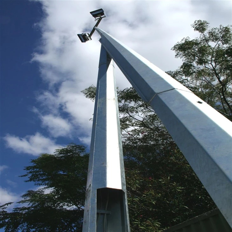
Mid-hinged lighting column — a connection example.
↔ Swipe horizontally to read all columns.
| Component / arrangement | Function to identify | Evidence for that function |
|---|---|---|
| Hinge and pin | Defines the rotational axis | Connection drawing, bearing details and design loads |
| Travel stop / limiter | Restricts travel at a designed position | Contact geometry and permitted loading condition |
| Structural securing arrangement | Restrains the working configuration | Load path, fastener / latch specification and verification |
| Access lock / padlock | Restricts unauthorized access or release | Stated purpose and relation to structural securing parts |
One component may serve several functions in a particular design. A stop surface may participate in the upright load path if designed for it. Establish that role through the assembly design; a visible contact surface does not prove capacity.
International Utility Poles’ TP-007 guide identifies four securing bolts and a separate padlock in its mid-hinged assembly. Those are features of its design, not a bolt count or operating instruction for another pole. [1]
A connection resists a moment through forces acting at a separation. In an ideal couple, M = F × d, so F = M ÷ d. Moving a restraint closer to its opposing reaction can increase the force needed to resist the same moment.
Illustrative static example: a 500 N·m moment is resisted by an ideal force couple. Compare effective separations of 0.10 m and 0.20 m. This explains leverage; it does not size a pin, bolt, weld or latch.
↔ Swipe horizontally to read all columns.
| Assumed moment | Effective separation | Ideal couple force |
|---|---|---|
| 500 N·m | 0.10 m | 5,000 N |
| 500 N·m | 0.20 m | 2,500 N |
▤ Read the result at the connection level
Doubling the effective separation halves the ideal couple force here. Real connections involve contact, stiffness, prying, bolt preload, tolerances and load combinations. These values are not allowable hardware loads.
The drawing therefore needs more than an external shaft diameter. Show the hinge axis, contact faces and restraint positions that create the load path. A replacement latch with the same nominal thread can still change the geometry or engagement.
The working configuration carries its specified operational loads. During movement, the assembly angle and weight distribution change. A winch, counterbalance or other control device must suit that moving configuration. A padlock does not control descent, and a travel stop should not be assumed capable of arresting uncontrolled movement.
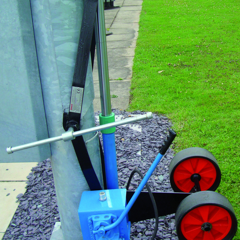
Ground-level lowering equipment beside a hinged pole.
TP-007 also warns that changes to counterweights or luminaire weights require manufacturer consent for its assembly. This illustrates why a lighting retrofit must include the lowering system in its review. A heavier head or longer bracket can affect more than the static shaft load. [1]
Identify the upright joint position, folding direction and attachment points for the specified operating equipment. Check how cables pass through or around the moving connection and avoid pinching, abrasion and excessive bending. Electrical bonding across moving parts needs the designed arrangement as well.
Specify corrosion protection and access for inspection. Coating build, wear or debris can affect fit and contact; replacement or repair must preserve the intended geometry. Include the approved inspection and maintenance instructions with the assembly.
During procurement, request a connection section that identifies each part’s function. During handover, retain the matching assembly revision and operating instructions. A drawing for a similar-looking pole cannot establish the supplied joint’s load path.
Only where the manufacturer design explicitly provides that function. An access padlock may prevent tampering while separate fasteners or latches provide structural restraint. Identify the load-bearing components before making a substitution.
A stop limits motion within its designed arrangement. A clear operating area, controlled lowering method and verified component capacities remain separate checks for the installed system.
Discuss your project with Jieyao Lighting
Send the required height, installed equipment masses and positions, folding direction and connection drawings. Describe the required locking and operating arrangement so the complete interface can be reviewed. Explore Jieyao lighting poles or use the website contact form to share the project requirements.
1. International Utility Poles, TP-007 — Manufacturer-specific reference identifying securing bolts, a separate padlock and restrictions on counterbalance changes. It is not an operating procedure for other products.
https://www.iupoles.com/doc/tp007-mid-hinged-pole/
The numerical examples are original calculations by Jieyao Lighting using the stated assumptions. They illustrate a comparison method and are not measured results for a supplied product.
Contact Us
Get a custom lighting solution and quotation for your project. Yangzhou Jieyao Lighting Equipment Co., Ltd. manufactures outdoor lighting and steel poles in Guoji Town Industrial Park, Gaoyou City, Yangzhou, Jiangsu, China. The company reports a 10,000 m² factory site, more than 60 employees including more than 10 technical personnel, and more than 100 production and testing machines. The present company name dates from 2017; Jieyao Poles’ published history traces the team’s manufacturing lineage to 2006. The stated 15 years of experience refers to the team. The company reports exports to more than 60 countries. Do you have any questions or requests?
Email: jay@jieyaolighting.com

Click to Chat.
Im online now.
 English
 Español
 Bahasa Indonesia