
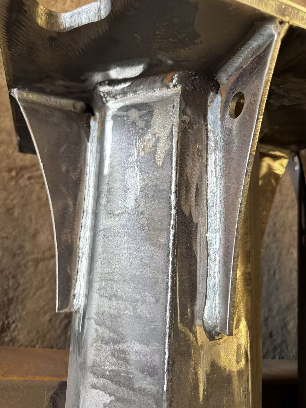
Remove weld slag, unsuitable residues and sharp projections, inspect the cleaned joints against the fabrication drawing, and preserve the specified weld size. Grinding should prepare the surface for inspection and coating without cutting away the designed connection. Check baseplate welds, gussets, shaft seams and galvanizing openings before releasing the pole for surface treatment.
A pole can have a neat painted base while the useful manufacturing evidence sits underneath the finish. For a buyer, the important question is what was checked while the welds were accessible: their location, dimensions, surface condition and the inspection required for the actual joint.
This guide uses Jieyao’s manufacturing photographs and technical method statement to show how those checks fit together. It focuses on new steel lighting poles before hot-dip galvanizing, with a separate check after coating. The photographs show connection details at different manufacturing stages; they are not a before-and-after sequence of one pole.
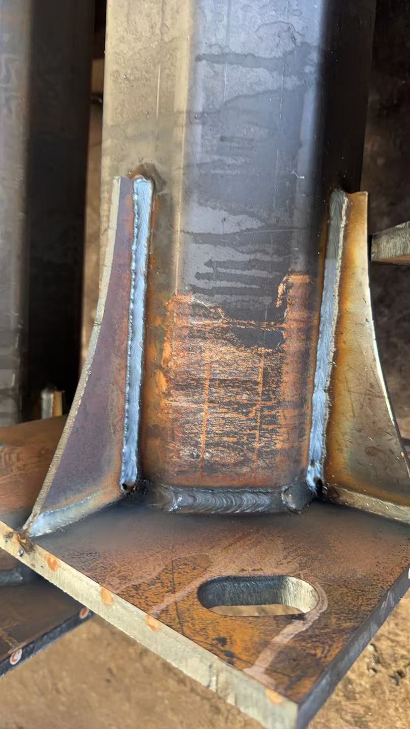
Steel pole baseplate and gusset welds before surface treatment.
A shaft seam, a gusset fillet weld and a shaft-to-baseplate joint perform different jobs. Their required size and penetration follow the structural detail and applicable welding procedure specification (WPS). A thick baseplate does not, by itself, tell an inspector what weld size to accept.
At the base, review the shaft perimeter and the gusset connections as separate inspection locations. A clear overall photograph establishes orientation. Close-ups of both sides of a gusset then show the surfaces that may be hidden in an overall view. Record the pole or component ID alongside the drawing revision so the photographs can be matched to measurements.
↔ Swipe to see every column · keyboard: focus the table and use arrow keys
| Location | What to check before coating | Evidence to retain |
|---|---|---|
| Shaft-to-baseplate joint | Specified weld detail, continuity, accessible surfaces and base alignment | Drawing detail, dimensional record and inspection result |
| Gusset-to-shaft / baseplate joints | Weld extent, leg or throat requirement, starts and stops, access between gussets | Joint IDs, gauge readings where applicable and close-up photographs |
| Longitudinal shaft seam | Specified seam type, surface condition and alignment along the shaft | Production procedure and the required seam inspection record |
| Door frames and welded attachments | Location, specified welds, distortion and functional clearance | Fabrication dimensions and door / attachment checks |
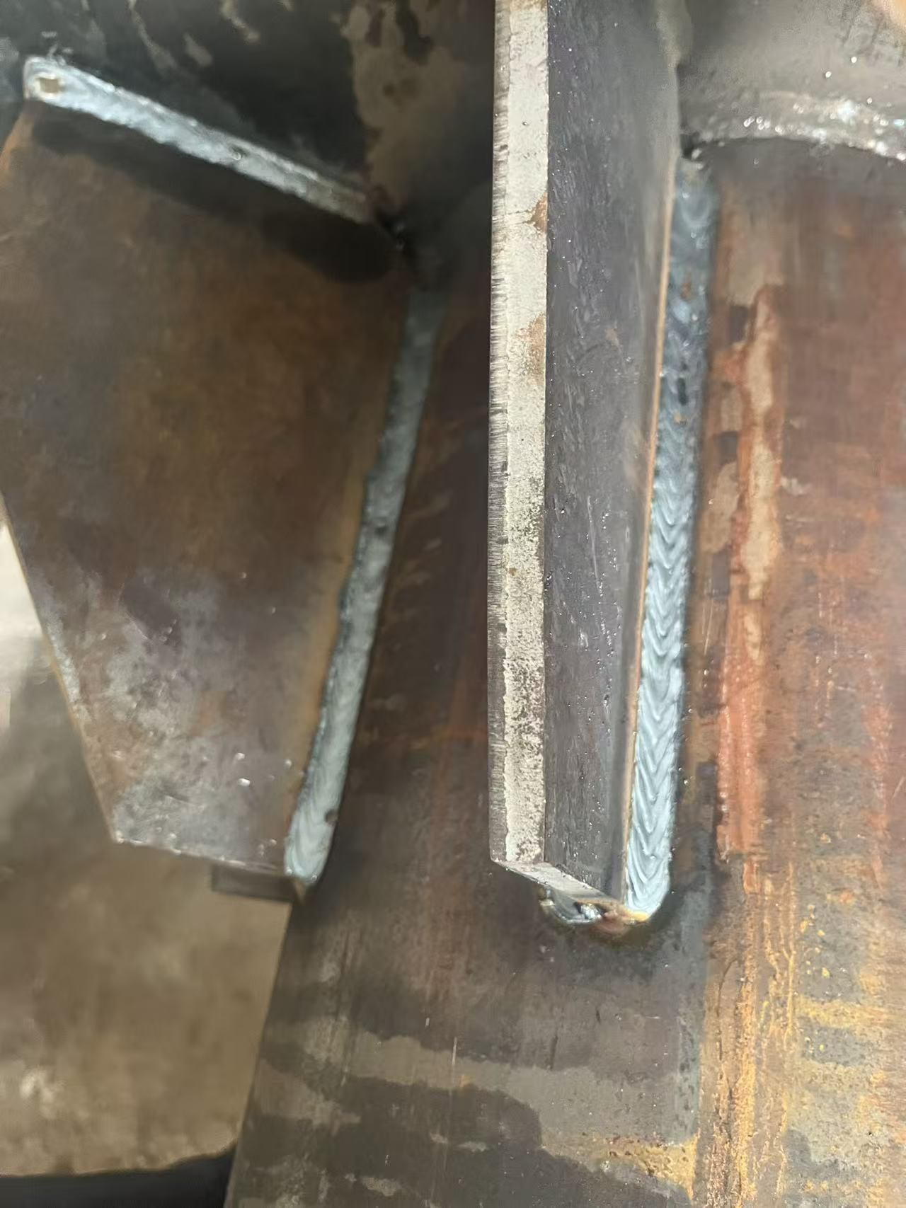
Gusset-to-shaft welds viewed from beside the base connection.
Specify the required weld profile before deciding how much to grind. Removing loose slag and sharp projections has a different purpose from grinding a joint flush. A gusset fillet weld needs its designed section; treating every raised bead as excess metal can remove useful weld material.
The drawing should distinguish an appearance requirement from a structural weld requirement. Where a particular contour or finishing treatment is specified, production and inspection need to verify that detail after finishing. Grinding marks alone do not demonstrate an acceptable joint, and an attractive surface does not establish internal penetration.
TWI explains that fillet-weld size depends on the required leg dimensions or throat thickness. It also notes practical limits on inspecting some fillet joints with volumetric methods. That makes the specified detail and an appropriate inspection plan more useful than a universal demand to make every weld look smooth. [2]
Consider an assumed equal-leg, flat-faced 90° fillet weld. Its ideal geometric throat is leg length ÷ √2. A 6 mm leg gives a 4.24 mm throat; a 5 mm leg gives 3.54 mm. If the effective length stays 100 mm, the ideal throat area falls from 424 to 354 mm² — about 16.7%.
This comparison explains why material removal deserves dimensional control. It is not a measurement of the photographed poles, an allowable grinding depth or a connection-capacity calculation. Actual root conditions, profile and the governing design determine acceptance.
↔ Swipe to see every column · keyboard: focus the table and use arrow keys
| Equal leg length | Ideal throat | Assumed effective length | Ideal throat area |
|---|---|---|---|
| 6.00 mm | 4.24 mm | 100 mm | 424 mm² |
| 5.00 mm | 3.54 mm | 100 mm | 354 mm² |
Weld beads and locally dressed surfaces at a gusset connection.
Cleaning begins with identifying what the welding process leaves behind. Flux-based processes can leave slag; bare-wire processes have a different residue profile. The American Galvanizers Association explains that the normal chemical cleaning used in galvanizing does not remove weld flux and slag. Those deposits need suitable removal before immersion. [3]
Use the specified cleaning method for the deposit and the access available. The objective is a clean, inspectable weld and surrounding surface. Check the tight spaces beside gussets, at starts and stops, and around intersecting welds. Slag caught in a corner should not be passed on in the expectation that the galvanizer’s pickling stage will remove it.
Spatter and sharp projections also affect the finish and handling. Remove them as required by the fabrication and coating specification while preserving the surrounding steel and weld. The cleaning review should cover any anti-spatter product or marking material that might remain on the surface, including whether it can be removed by the planned pretreatment.
Baseplates, stiffeners and hollow sections also need a galvanizing layout that allows air, pretreatment liquids and zinc to pass through the assembly. The AGA identifies gussets and baseplates as details where drainage needs attention. [4] Confirm the openings against the coordinated fabrication drawing and galvanizer’s requirements; do not add a generic hole size copied from a different pole.
A weld can be clean while a nearby enclosed pocket still has an unsuitable drainage arrangement. Inspecting both at the release stage helps avoid sending an otherwise finished assembly back for modification.
For the wider examination scope, see our weld inspection and NDT scope guide. This guide focuses on weld finishing and release before galvanizing.
Jieyao’s technical method statement calls for visual examination of all accessible structural welds before coating. That is the stated inspection scope for the method; a project’s signed records establish what was actually examined. Additional non-destructive testing (NDT), its extent and its acceptance criteria follow the design and inspection plan.
For a practical buying specification, name the joint, the applicable standard and edition, the drawing revision and the required report. Where AWS D1.1 is specified, the applicable requirements still depend on the actual joint and loading category. A general mention of AWS D1.1 in a brochure does not supply those project details.
↔ Swipe to see every column · keyboard: focus the table and use arrow keys
| Check | Record to request | What it answers |
|---|---|---|
| Material and procedure | Material identification, applicable WPS ID and welder qualification | Was the joint made under the specified production basis? |
| Weld dimensions and surface | Joint location, required size, readings and visual examination result | Does the accessible finished joint match the detail? |
| Specified NDT | Method, coverage, location, report and acceptance basis | Was the required additional examination completed? |
| Repair and reinspection | Defect location, approved repair route and reinspection result | Was an identified issue closed before release? |
| Fabrication geometry | Straightness, flange flatness, hole positions and attachment function | Will the manufactured component fit its intended interface? |
Magnetic-particle or penetrant examination can address specified surface discontinuities; ultrasonic or radiographic examination may be appropriate for suitable joints. Select the method with the inspection specialist for the actual geometry and access. A request for “100% UT everywhere” without defining the joint can be difficult to execute or interpret.
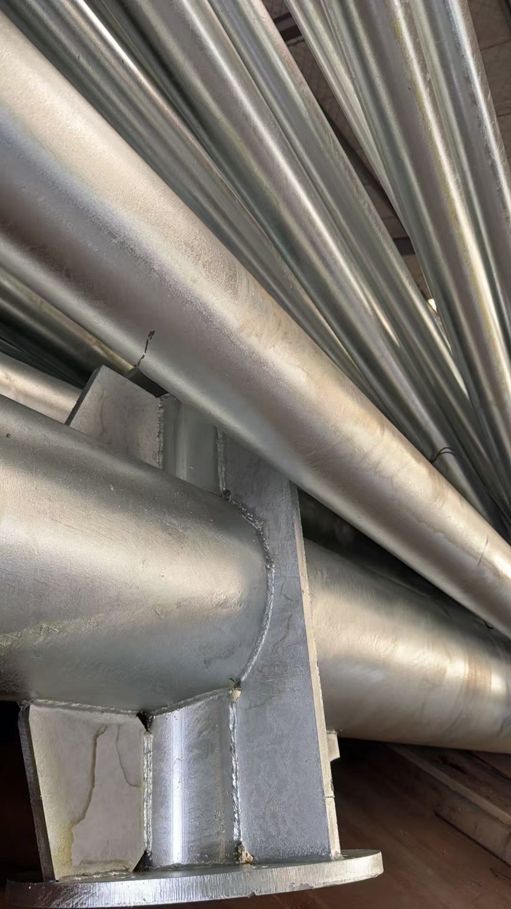
Galvanized pole base connections and reinforcing gussets.
The post-galvanizing check has a different purpose: examine the coating around the connection, its specified thickness and condition, and any repairs. A raised or darker weld line may have a metallurgical explanation. The AGA notes that weld-metal chemistry can change zinc growth, so grinding a weld smooth before galvanizing does not guarantee an invisible weld afterwards. [5]
Assess the finish against the agreed coating requirements rather than using color uniformity as a structural test. For a painted galvanized pole, keep zinc and organic-coating evidence separate. A combined thickness reading alone does not identify the thickness of each layer.
Our five-coat marine pole coating guide develops the coating schedule and its evidence. This weld-inspection guide covers the earlier fabrication release, so the two pages answer different procurement questions.
After the finish reaches its specified handling cure, protect baseplate edges and projecting gussets from straps, metal contact and impact. Record any coating damage and complete the specified repair before dispatch. Preserve the component identification through wrapping so the delivery can still be connected to its inspection file.
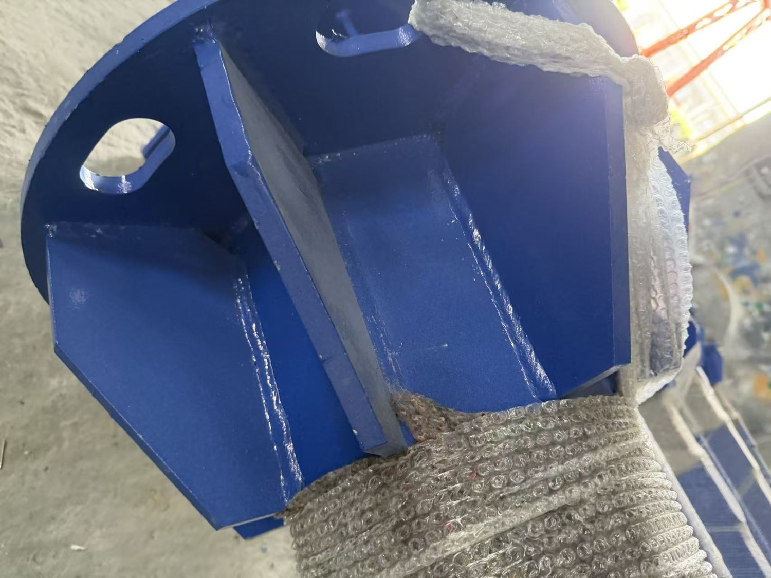
Coated baseplate and gussets with packing protection.
Sixteen checks covering document review, weld dimensions, cleaning, galvanizing readiness and final protection. Includes space for the pole ID, drawing revision, evidence references, observations and follow-up responsibility.
Download the inspection checklist · PDFBlank worksheet · English · Rev 1 · 7 November 2026. Use with the approved drawings, WPS and project inspection plan.
A surface photograph shows accessible appearance and arrangement. Penetration needs evidence appropriate to the joint and specified inspection method. Ask for the procedure, joint detail and required examination records.
Weld size follows the connection design, materials, geometry and loading. Pole height or baseplate thickness alone is insufficient to set a universal size.
Here it means preparing fabricated steel pole joints for inspection and hot-dip galvanizing. Processes used to clean heat tint from stainless steel address a different substrate and finish.
For a Jieyao steel-pole inquiry, send the pole arrangement, base connection detail, material specification, coating exposure and required inspection or third-party witness stages. Agree the manufacturing and document requirements before production, including any appearance-sensitive areas. That makes the release criteria visible to both the supplier and buyer.
For moving assemblies, our hinged and tilting light pole manufacturing guide explains the additional hinge and movement interfaces. Explore Jieyao folding pole configurations or send your pole drawing and inspection brief.
Reference URLs:
[2] https://www.twi-global.com/technical-knowledge/job-knowledge/fillet-welded-joints-a-review-of-the-practicalities-066
[3] https://galvanizeit.org/knowledgebase/article/weld-slag-clean-up-requirements-for-galvanizing
[4] https://galvanizeit.org/designing-for-hot-dip-galvanizing/design-fabrication/venting-drainage/gusset-and-base-plates
[5] https://galvanizeit.org/knowledgebase/article/welding-appearance-after-hdg
The fillet-weld table is Jieyao’s illustrative geometry calculation using stated assumptions. It is separate from the pictured components. External references accessed 7 November 2026. Project acceptance follows the specified standards and approved documents.
Contact Us
Get a custom lighting solution and quotation for your project. Yangzhou Jieyao Lighting Equipment Co., Ltd. manufactures outdoor lighting and steel poles in Guoji Town Industrial Park, Gaoyou City, Yangzhou, Jiangsu, China. The company reports a 10,000 m² factory site, more than 60 employees including more than 10 technical personnel, and more than 100 production and testing machines. The present company name dates from 2017; Jieyao Poles’ published history traces the team’s manufacturing lineage to 2006. The stated 15 years of experience refers to the team. The company reports exports to more than 60 countries. Do you have any questions or requests?
Email: jay@jieyaolighting.com

Click to Chat.
Im online now.
 English
 Español
 Bahasa Indonesia