


Choose pole geometry, material, finish, mounting, foundation and maintenance access from the actual site layout, luminaire data and project design basis.
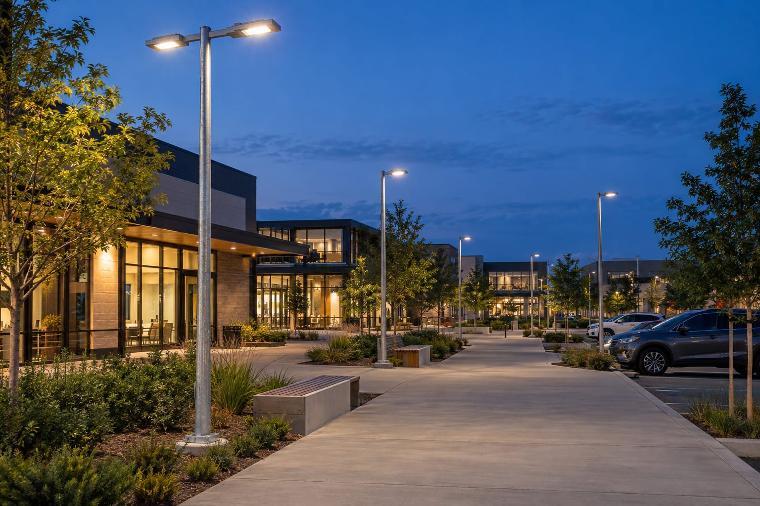
An outdoor pole is one part of a lighting, structural, electrical and civil system. The same catalogue description can lead to different physical products when the fixture arrangement, wind basis, corrosion exposure, mounting height, access openings or foundation interface changes. Start with the site layout and required function, then define the pole that connects those requirements.
This guide covers parking areas, campuses, pedestrian precincts, parks, hospitality grounds and commercial developments. Roadway projects have separate traffic, clearance and lighting considerations; use the street light pole height guide when the primary task is road mounting-height selection. Keeping these intents separate produces clearer specifications and more useful search destinations.
Mark parking bays, drive aisles, loading areas, building entrances, walkways, stairs, plazas, service yards, landscape areas and sensitive boundaries. Each zone has a different relationship among vehicles, pedestrians, façades, trees and maintenance access. One pole type can sometimes serve several zones, but that should be confirmed by the layout rather than assumed at the start.
Record finished levels, curbs, islands, ramps, retaining walls and planned planting. Identify where poles are prohibited because of vehicle swept paths, emergency routes, accessible paths, utilities or architectural sight lines. A zoned plan allows the designer to compare perimeter poles, interior poles, wall-mounted luminaires and low pedestrian-scale units without hiding conflicts inside a single average lighting target.
Define the governing project requirements, calculation method, grid, maintenance assumptions and any limits for uniformity, glare, spill light or obtrusive light. The relevant values depend on the authority, site use and applicable standard. A product page cannot determine them without the project context, and wattage alone cannot show where a luminaire distributes light.
Use the proposed fixture's current photometric file, output, optic, tilt and orientation. Model façades, canopies, trees and level changes that may obstruct or redirect light. Review entrances, crossings, payment areas, loading edges and other conflict locations separately. The preferred layout should meet the whole brief, not only produce a high average at the easiest point to calculate.
Mounting height changes the fixture coordinate, while spacing controls how neighboring distributions overlap. Raising a fixture can broaden coverage with a suitable optic, but may also change glare, visual scale, structural demand and the equipment required for service. Lower units can provide more local control yet may require additional locations and cable routes. Neither direction is automatically better.
Test coordinated options using the same criteria and site geometry. Record every change to luminaire, optic, output, tilt, pole line and head arrangement. The site may justify different mounting heights for open parking and a pedestrian courtyard, but unnecessary variation increases drawing, production, foundation, spare and maintenance complexity. Each type should solve a defined condition and carry a clear schedule mark.
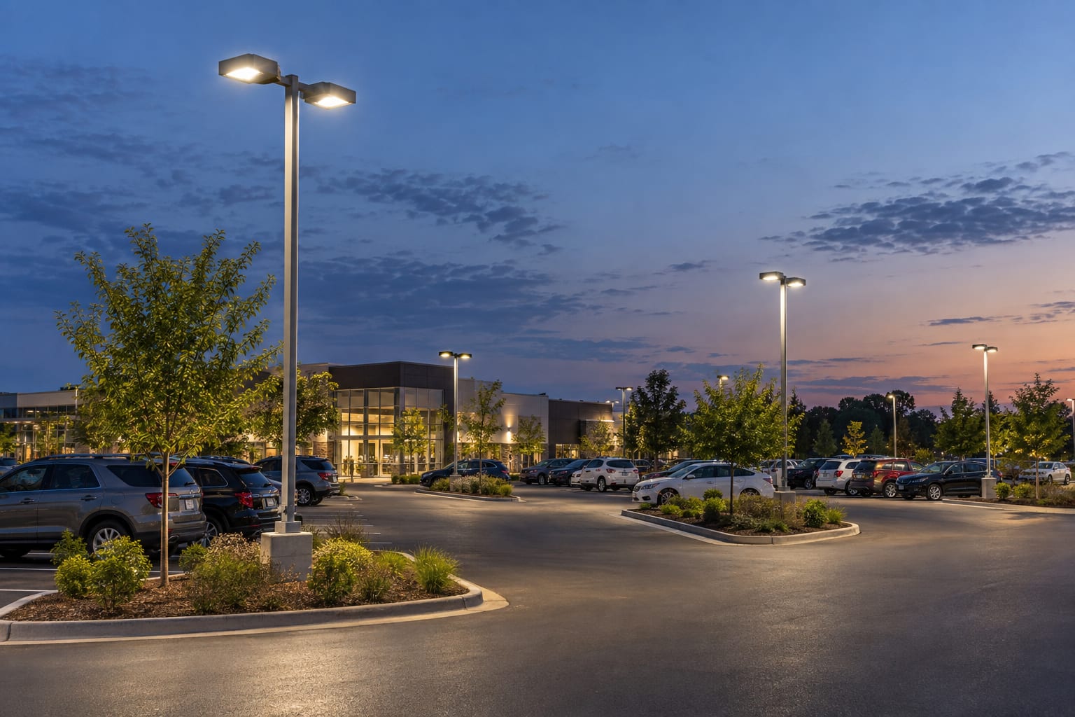
Parking areas are two-dimensional grids, not simplified road corridors. Pole positions affect bays, turning movements, accessible routes, snow or cleaning operations, drainage and landscaping. Place bases within properly designed islands, behind barriers or outside vehicle paths as the site plan permits. Check door orientation and service access so a technician does not need to stand in an active aisle.
Interior poles can support multiple luminaires and reduce edge-to-center distance, while perimeter poles may simplify civil work in some layouts. The comparison must include photometric performance, projected area, torsion from asymmetric heads, foundation reactions, cable routing, impact exposure and maintenance. The galvanized parking lot light pole page provides the corresponding product-focused route.
Campus paths and pedestrian precincts place people close to the pole and luminaire. Review visual comfort, face recognition needs where required by the brief, vertical surfaces, steps, crossings and the transition between bright entrances and quieter paths. Keep shafts, doors and base projections out of the clear walking route, and coordinate with accessible-width and edge-protection requirements.
Trees are a frequent source of conflict. Show mature canopy size, root zones and pruning access rather than relying on the construction-day landscape. Avoid placing a luminaire inside future foliage or placing a foundation where it conflicts with roots and irrigation. Lower pedestrian-scale poles may suit the desired character, but their quantity, cable network, glare control and vandalism exposure still need project-specific review.

Parks, resorts, civic gardens and hospitality entrances often use the pole as a visible architectural element. Establish the intended form, color, gloss, scale and daytime appearance with the landscape or architectural team. Decorative collars, bases and arms must still provide credible load paths, drainage, cable access and a maintainable connection to the luminaire.
Avoid choosing ornament from a small rendering without dimensioned details. Confirm shaft profile, decorative component material, fastening method, access-door integration and finish boundaries. Water should not collect at sleeves or concealed interfaces. The decorative galvanized lighting pole page is the commercial destination for custom appearance, while this guide retains the broader selection context.

Retail streets, office entries and mixed-use developments often place poles near glazing, signs, canopies, residences and public roads. Review light toward windows and property boundaries, not only the ground calculation grid. A shield, lower tilt or different optic may solve a boundary condition more effectively than moving the pole after foundations and landscaping are coordinated.
The daytime arrangement also matters. Align pole families with architecture without creating conflicts with storefront visibility, loading doors, fire access or pedestrian desire lines. If banner arms, cameras, speakers or wayfinding are planned, list them as equipment rather than treating them as later accessories. Their area, mass, cable routes and maintenance requirements can change the pole design.
Industrial outdoor light poles may sit beside truck routes, loading aprons, storage zones, fencing and process equipment. Use swept-path information and the owner's operational plan to keep bases and maintenance activities out of working space. Check whether stacked materials, future buildings or mobile equipment will obstruct light or prevent safe access to the pole.
Dust, chemicals, washdown, airborne contamination and vibration may influence finishes, hardware and luminaire selection. These conditions should be described in the inquiry rather than compressed into the word “industrial.” Separate the environmental exposure of the shaft, base, door, fasteners and electrical components, and identify who approves each part of the specification.
The same pole catalogue can serve very different outdoor zones only after the local optical, structural and access conditions are mapped. This zone table is a screening aid rather than a fixed height or spacing schedule.
| Outdoor zone | Lighting/site review | Pole and service review |
|---|---|---|
| Parking area | Bays, vehicle paths, islands and boundary spill | Protected base, multi-head loads and maintenance access |
| Campus or walkway | Pedestrian routes, glare, trees and accessible width | Door position, visual scale and cable routing |
| Landscape/frontage | Architecture, glazing, canopy and property line | Finish, ornament loads and removable-cover inspection |
| Service yard | Truck swept paths, storage, operations and contamination | Collision clearance, coating details and lift-truck access |
Material selection is not a universal ranking. Steel and aluminum use different grades, fabrication details, section sizes, connection practices and corrosion strategies. Compare the complete designed assemblies for the required geometry, loads, exposure, finish, procurement scope and maintenance plan. A generic statement that one material is always stronger, lower-cost or more durable hides the variables that actually control the decision.
Jieyao's relevant product cluster is based on fabricated steel lighting poles, so proposals should clearly state that manufacturing scope. Where a project is evaluating another material, the responsible designer should compare code provisions, alloy or grade, temper, weld details, galvanic interfaces, anchorage and finish compatibility. Do not substitute one material into a drawing prepared for another without a new review.
Round, octagonal and square tapered shafts create different architectural expressions and fabrication interfaces. Shape can influence seam placement, door detailing, arm alignment, base geometry and how the pole reads against a building. It does not independently prove capacity. The structural schedule still follows the complete loads, openings, material properties and governing calculation method.
Octagonal and square tapered steel poles can serve different architectural and interface requirements when those shapes match the procurement intent. If visual continuity is critical, approve representative geometry and finish samples before quantity production, then control door orientation and seam direction on the site plan.
A steel pole acts as a cantilevered support. Its response depends on height, taper, section, wall schedule, steel properties, openings, welds, joints, arm geometry, equipment and connection details. Two poles with the same nominal height and thickness can have different capacities because their loads, diameters, base details or door arrangements differ.
Provide the governing standard and edition, design actions, wind-speed definition, terrain or exposure, topography, importance requirement and any other applicable conditions. The responsible structural process should return a coordinated shaft, base and reaction set. Marketing labels such as “heavy duty” or a wind number without its definition are not substitutes for that design basis.
List each luminaire's mass, effective projected area, center of gravity, mounting position and orientation. Include arms, tenons, adaptors, cameras, signs, banners or other approved items. A twin-head parking pole and a single-head walkway pole impose different bending and torsional effects even when their shafts share a nominal height.
Future accessories need a defined load and location envelope if they are to be accommodated. An undefined promise of spare capacity cannot be checked. Where the site genuinely combines lighting, signals, communications or monitoring equipment, review whether a purpose-designed multi-function pole is more appropriate than adding components to a conventional lighting shaft later.
A flanged pole transfers actions through a base plate and anchors into a designed support. A direct-burial pole transfers them through an embedded section and its surrounding material. Neither method is universally correct for every outdoor site. Consider soil, groundwater, frost, drainage, pavement, utility congestion, erection access, replacement strategy and the responsible civil designer's requirements.
For flanged poles, coordinate bolt pattern, anchor projection, conduit, leveling method, grout or bearing detail, finished level and orientation. For embedded poles, define embedment, cable entry, surround, drainage and soil-contact protection. Review the foundation and anchor bolt guide before releasing either interface.
The pole supplier can provide geometry and design reactions for the agreed assembly, but the support must respond to local geotechnical and civil conditions. A foundation copied from a different location or a pole of similar height may not suit the soil, groundwater, slope, pavement, scour or loading at the new position.
Define the responsibility boundary in the documents. Show what the pole package supplies, what the civil designer sizes, what the installer sets and what information must be exchanged. This avoids a gap where plate and anchor dimensions are fixed before reactions exist, or civil concrete is cast before the final conduit and orientation are known.
Describe atmospheric, soil-contact and local splash conditions instead of selecting a finish from the site name alone. Coastal air, deicing salts, industrial contaminants, irrigation, standing water and trapped debris can create different exposures at the shaft, base, fasteners and decorative interfaces. The project specification should identify the applicable preparation, coating system, inspection and repair requirements.
Hot-dip galvanizing provides a zinc coating on fabricated steel, while an organic topcoat can add color and another barrier when a compatible duplex system is specified. Performance depends on design, preparation, application, environment, damage and maintenance. Avoid publishing a fixed service-life multiplier without a defined system and exposure. Drainage-aware geometry is as important as the coating name.
A seafront label does not by itself define distance from salt sources, prevailing weather, shelter, wetting, cleaning or deposition. Provide the environmental classification used by the project and identify local conditions such as salt-laden spray, sand abrasion or frequent washdown. Resolve base clearances, drainage paths, fasteners and dissimilar-metal contacts before selecting the final coating schedule.
Color-coated poles require clear handling and repair instructions because lifting, transport and installation can damage the organic layer. Inspection should cover coverage, continuity and agreed appearance without making unsupported lifetime promises. The coastal duplex-coated pole page provides a focused route for steel poles requiring galvanizing plus a compatible color coat.
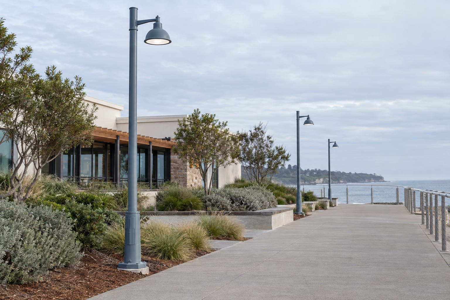
A color name on a screen is not a complete appearance standard. State the agreed color reference, gloss range where required, texture, visible surface expectations and sample approval process. Lighting conditions, substrate, coating batch and viewing distance can change perception. Use a physical sample or approved reference appropriate to the project before production.
Define which components receive the finish: shaft, arm, base cover, door, fasteners or decorative pieces. Masked threads, grounding points, slip joints and mechanical interfaces may require different treatment. Show transitions clearly so coating is not added where it prevents fit or omitted from visible zones that the architectural team expects to match.
The service opening interrupts the shaft and therefore belongs in structural detailing, not only electrical coordination. Define its size, height, orientation, reinforcement, cover, fastening and sealing approach. Confirm that the electrical equipment fits and can be reached without conflicting with landscaping, parked vehicles, pedestrian flow or another pole component.
Door orientation should appear on the site plan and pole schedule. In parking areas, access may face away from traffic; near walls or planting, sufficient working clearance is needed. Avoid rotating a flanged pole in the field to solve door access because this may misalign arms, bolt patterns, photometric orientation or asymmetric structural details.
State the tenon or spigot dimensions, insertion depth, orientation, fasteners, anti-rotation method, cable path and permitted fixture adjustment. The pole drawing and luminaire data must describe the same interface. A fixture that physically slides onto a tube is not necessarily approved if engagement, tilt or fastener positions differ.
For detachable arms, show how each piece is marked and assembled. For multiple luminaires, dimension every bracket direction from a common datum. Ensure the structural load schedule uses the same arrangement that the photometric model uses. Late substitutions require review of fit, optical position, mass, projected area and center of gravity before shipment or installation.
Check delivery access, unloading area, lifting points, crane position, overhead hazards and temporary exclusion zones. Long poles need a realistic path from vehicle to foundation without passing through buildings, trees or active public areas. Segment joints, when used, need defined engagement, orientation and an approved assembly procedure.
Maintenance planning should identify how technicians reach the luminaire and door, where access equipment stands and whether traffic or pedestrian controls are required. Keep records of the approved fixture, arm and structural load basis so replacements can be checked. The street light pole installation guide covers receiving, erection, alignment and handover in more detail.
The site plan, photometric layout, pole schedule, general arrangement, arm drawing, base detail and foundation information should use common type marks and revisions. State mounting-height references, fixture coordinates, door direction, finish, equipment and base orientation. Remove superseded documents from active procurement and site work packs.
Review comments should identify the drawing, revision and responsible party. Close issues that affect geometry or loads before production rather than relying on a note to resolve them on site. The shop drawing checklist helps connect site, lighting, structural, electrical and civil information at the approval stage.
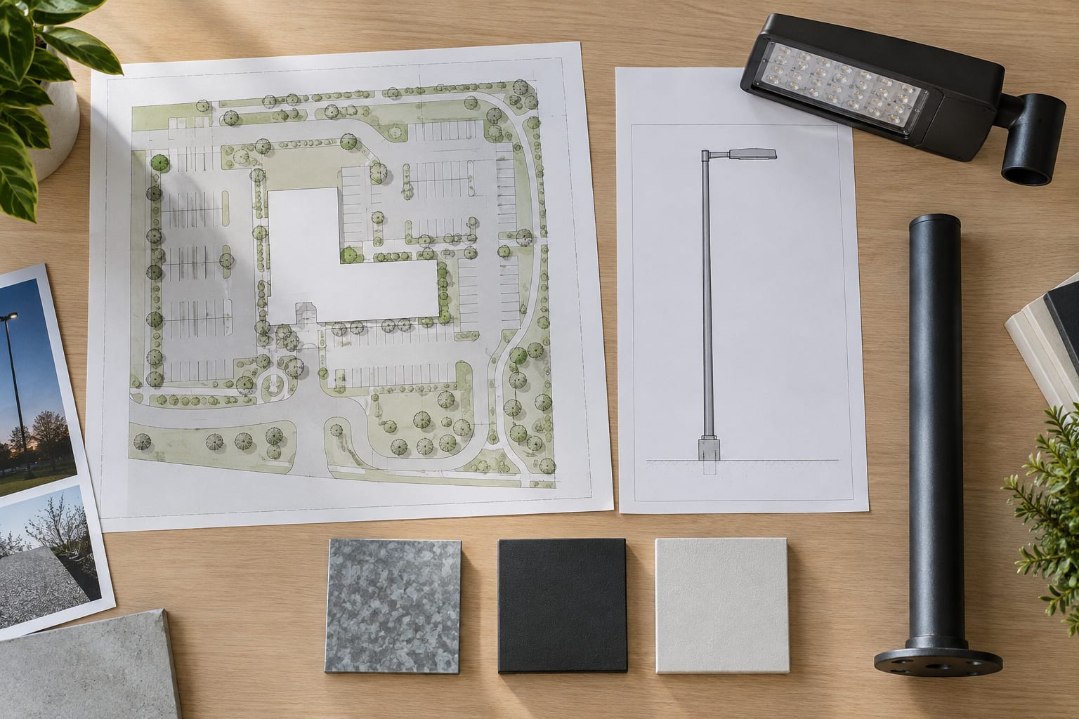
| Input group | Information to provide | Decision supported |
|---|---|---|
| Site and use | Layout, zones, levels, pole coordinates and obstructions | Pole families and locations |
| Lighting | Criteria, photometric file, output, optic, tilt and mounting height | Head arrangement and coordinates |
| Structure | Governing basis, wind definition, terrain, topography and attachments | Shaft, arm and reactions |
| Environment | Exposure classification, salts, contaminants, soil contact and color | Finish and detailing |
| Civil interface | Flanged or embedded concept, geotechnical context, conduit and levels | Base or embedment coordination |
| Delivery and records | Quantities, destination, packing limits, submittals and inspection points | Proposal and document scope |
Create a compliance schedule that lists geometry, material, finish, equipment loads, structural basis, mounting interface, base concept, documentation, inspection, packing and exclusions. Ask each supplier to identify deviations against the same requirements. A shorter description may conceal missing scope rather than represent an equivalent pole.
Check that quantity schedules use the same pole marks as the drawings and include arms, base covers, anchors, templates and loose accessories where applicable. Separate included items from optional or third-party scope. This simple reconciliation prevents an apparently complete technical proposal from producing shortages, duplicated parts or incompatible site deliveries.
Do not reduce the comparison to unit cost. Review the number of pole types, foundations, site adaptations, replacement interfaces and documents needed to deliver the system. Commercial evaluation depends on local quantities, freight, civil work, installation, operation and risk allocation; avoid universal savings claims or fixed return calculations that are not based on the project.
A luminaire certificate does not automatically certify a pole, coating, anchor system or complete site installation. Define which component, model, standard, edition and report the project requires, then verify that the supplied document applies to the offered configuration. Do not publish certificate numbers or performance values unless the underlying documents have been checked and remain applicable.
Similarly, protection ratings for luminaire housings do not describe the structural pole. Electrical, mechanical, corrosion and photometric requirements belong to different evidence sets. A clear submittal register prevents one document from being presented as proof of unrelated properties and helps the reviewer identify missing information before shipment.
Use the actual photometric distribution, output, tilt and site geometry.
Test mounting height with optics, spacing, glare, scale and service access.
Protect bases and preserve turning, parking and emergency access.
Define exposure, preparation, compatible layers, details and repair.
List every head, arm, sign, camera and future attachment in the load basis.
Close luminaire, door, base, anchor, conduit and drawing details before production.
This process keeps each decision traceable. If the fixture, location, attachment, wind basis, finish or foundation changes, return to the affected design step and update the relevant calculation and drawing. The broader street light pole buying guide explains how to carry this information into sourcing and supplier comparison.
It is a structural support coordinated with luminaires, wiring, mounting and a civil foundation or embedment.
Start with site zones, lighting criteria, fixture data, loads, exposure, support and maintenance access.
Determine height from the photometric layout, optics, spacing, glare, structure and service method.
Yes, when the designed steel assembly, finish, scale and base details match the project.
The project must define exposure and a complete compatible coating, detailing, inspection and repair system.
Yes, if every head and bracket is included in photometric, structural and mounting reviews.
Choose from the site support strategy, soil, drainage, utilities, loads and replacement plan.
No. An enclosure rating applies to the identified enclosure, not the pole's structural capacity.
Only after checking load, position, cable route, access, pole design and foundation reactions.
Send the layout, fixture data, design basis, exposure, base concept, quantities and document scope.
Provide the site plan, pole coordinates, mounting-height reference, luminaire file and physical data, wind basis, exposure, finish, base concept, quantities and destination. Jieyao can organize a steel pole configuration and identify open interfaces for project review.
Discuss Your Outdoor Pole Schedule
Street Light Pole Height Guide: How to Select Moun
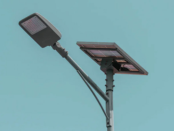
Integrated and Split Solar Street Lights Compariso
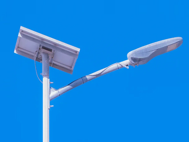
How to Choose the Right Solar Street Light Pole
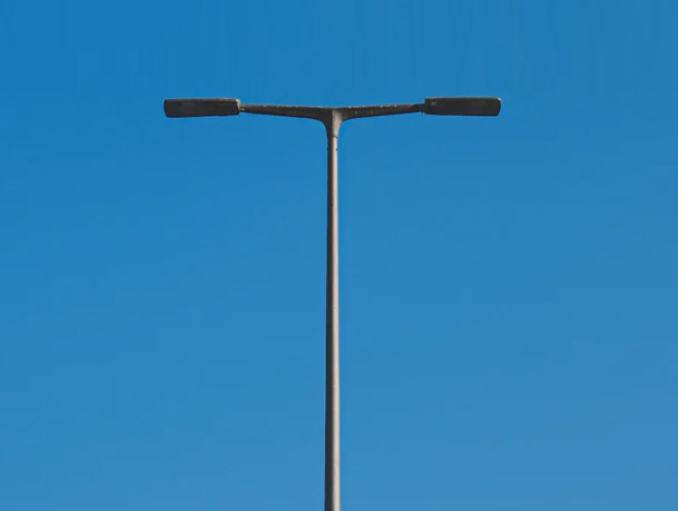
Street Light Pole Cost Factors and Quotation Compa
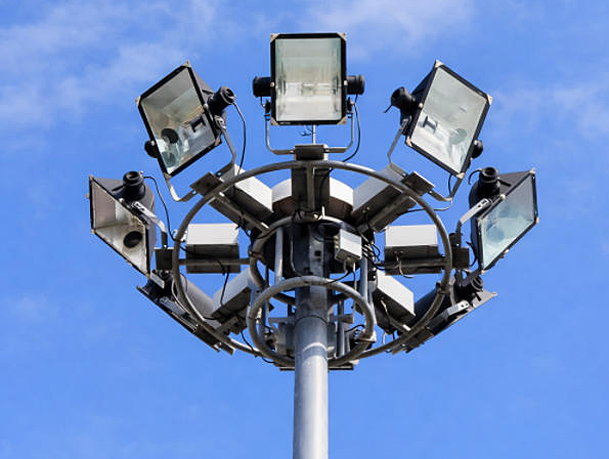
High Mast Light Specifications and Selection Guide
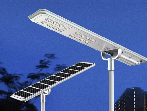
Features of All in One Solar Street Lights
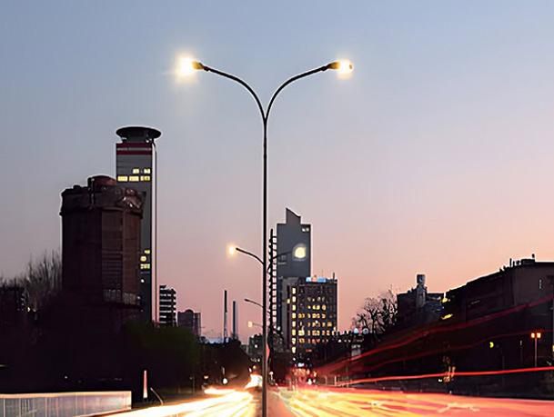
How to Choose the Right LED Street Lights for Your
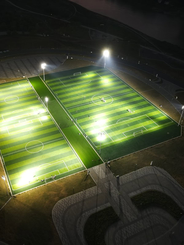
Select the Right LED Stadium Light for Football Pi
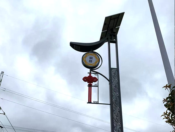
6-meter steel lamp post, 150W solar landscape ligh
Solar Street Lights Installed at Baybay Black Sand
Contact Us
Get a custom lighting solution and quotation for your project. Outdoor lighting manufacturer in Yangzhou, ChinaAbout Jieyao LightingYangzhou Jieyao Lighting Equipment Co., Ltd. is an outdoor lighting manufacturer focused on solar street light systems and high mas... Do you have any questions or requests?
Email: jay@jieyaolighting.com

Click to Chat.
Im online now.
Hey, I'm Xu Jie from Jieyao Lighting. What can I do for you? Welcome to contact me, WhatsApp: +86 13815843784
WhatsApp Us
🟢 Online | Privacy policy