


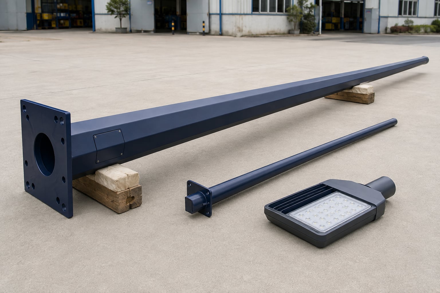
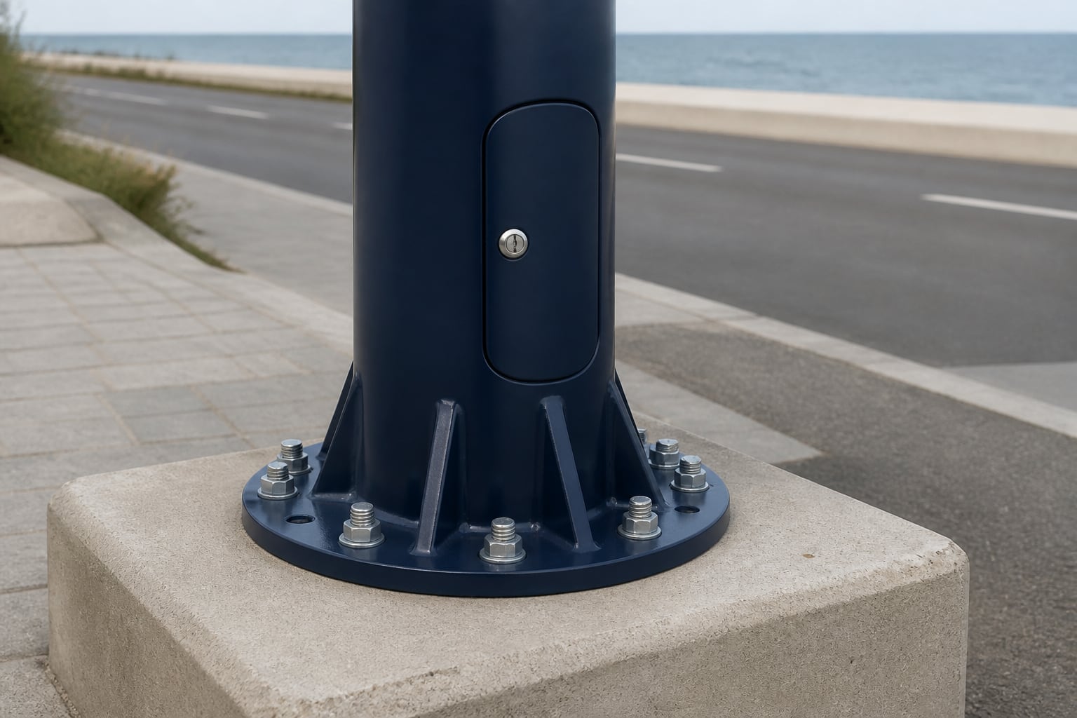
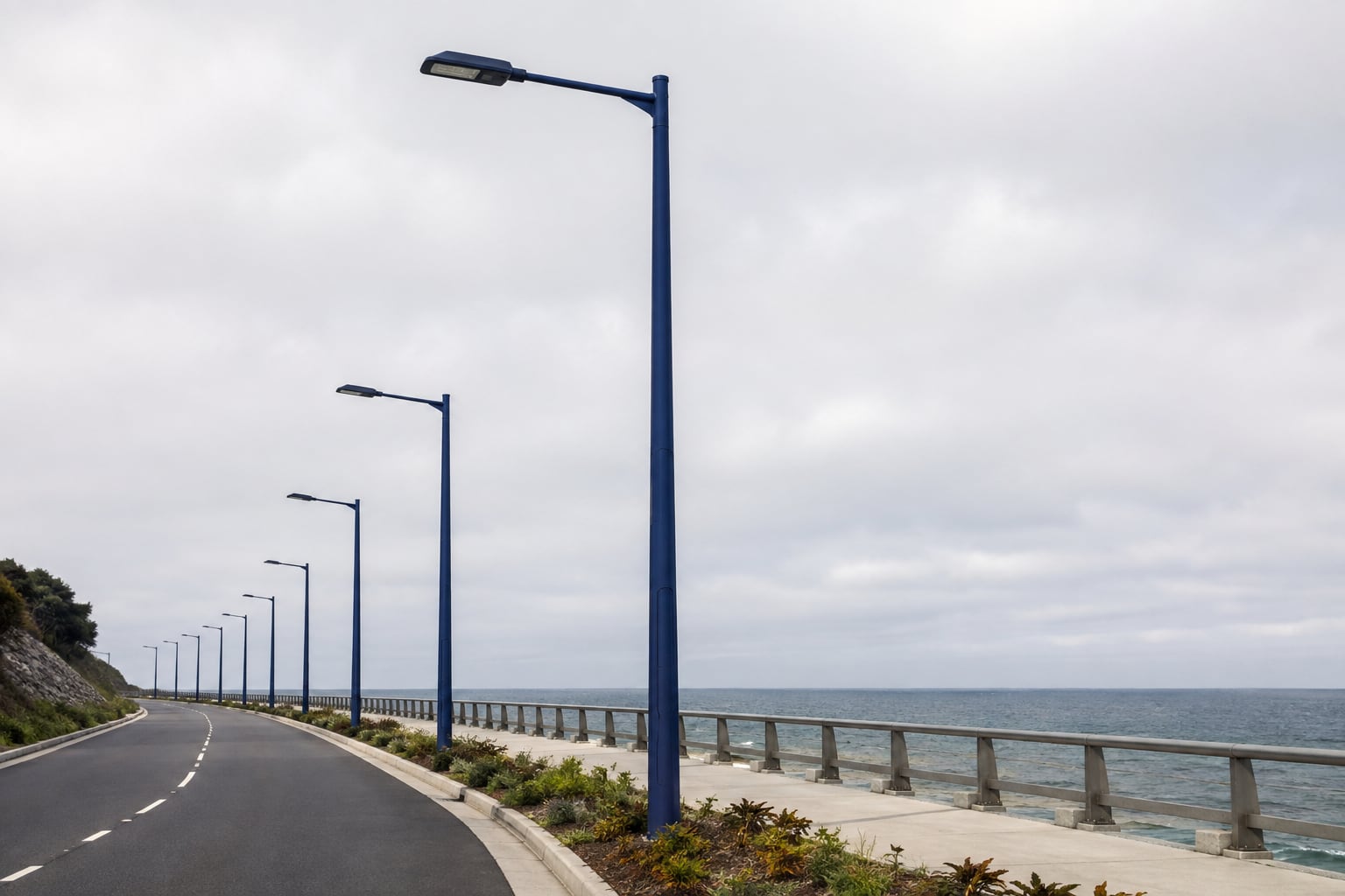
A project-configured steel lighting pole for seafront roads, port approaches and salt-exposed sites, combining hot-dip galvanizing with a compatible organic color coat. Shaft geometry, arms, access openings, bases, anchors, coating details and inspection records are coordinated around the actual exposure and project specification.
A coastal street light pole is not defined only by blue paint or by its distance from the shoreline. It is a structural lighting support whose material, drainage details, openings, fasteners and protective coating system are selected for a site where airborne salt, repeated wetting, high humidity or splash can accelerate corrosion. The same appearance can therefore represent very different supply scopes.
Jieyao treats the pole and its coating as one coordinated package. The purchaser provides the road layout, equipment loads, structural basis, environment description and coating requirements. The offered configuration then identifies the steelwork, galvanizing, organic topcoat, masking, inspection, packing and repair provisions included in the quotation. This makes technical comparison clearer and avoids relying on an undefined phrase such as “marine grade.”
Roads facing open water may receive wind-driven salt and frequent condensation even when poles are outside the direct splash zone.
Access roads near terminals can combine salt exposure, industrial deposits, heavy vehicles and restricted maintenance windows.
Transport limits and long replacement lead times can make coating definition, packing and repair planning important procurement issues.
Plant roads, logistics yards and perimeter routes may need color-controlled poles with project-specific access and equipment interfaces.
| Item | Configuration Direction | Buyer Input |
|---|---|---|
| Application | Roadside, median or area-lighting arrangement | Road section, pole coordinates and lighting layout |
| Exposure | Project-defined coastal or salt-laden environment | Shore distance, wind, splash, humidity and maintenance data |
| Pole | Tapered polygonal or approved round steel shaft | Height, loading, openings and governing standard |
| Top arrangement | Single arm, double arm or post-top interface | Luminaire dimensions, mass, EPA and mounting |
| Zinc layer | Hot-dip galvanizing to the agreed project requirement | Applicable standard and acceptance criteria |
| Organic coat | Compatible pretreatment, powder or specified liquid system | System data, color, gloss, thickness and repair method |
| Base interface | Flanged base and matched anchor cage | Foundation responsibility, levels and conduits |
| Documents | Drawings, coating records and packing information | Review stages and required submittal format |
The table describes configurable directions. Final dimensions, structural values and coating acceptance criteria follow the approved project documents.
For this product, duplex coating means a hot-dip galvanized steel substrate combined with a compatible organic finish. The zinc layer and topcoat perform different functions. Galvanizing provides a continuous zinc-based protective layer over suitably detailed steelwork, including surfaces that a sprayed color coat may not reach easily. The organic layer adds a specified color and can reduce direct exposure of the zinc surface when it is correctly prepared, applied and maintained.
The two layers must be treated as a system. Applying an attractive powder coat over unsuitable, contaminated or poorly prepared zinc does not create a controlled duplex system. The RFQ should therefore identify the galvanizing requirement, post-galvanizing condition, pretreatment, coating product family, cure conditions, thickness range, color reference, inspection and repair process. A supplier comparison should confirm each of these items rather than checking color alone.
A compatible organic coat can support architectural color control, visual integration with the roadway and an additional barrier between the zinc surface and the environment. This may be useful on promenades, resort access roads, port entrances or urban waterfronts where untreated galvanized appearance is not preferred. Color can also help an owner maintain a consistent streetscape across pole heights and equipment types.
The organic finish does not make structural design optional, and it is not a substitute for suitable drainage, access-door detailing, packing or maintenance. Its value depends on the complete specification and the real service environment. The buyer should define whether the same finish applies to shafts, arms, doors, brackets, base covers and exposed hardware, because partial color scope can create unexpected visual and maintenance differences.
Describe the location in practical engineering terms. Useful inputs include distance from open water, elevation, prevailing wind direction, exposure to surf or splash, seasonal storms, average humidity, rainfall pattern, condensation, industrial emissions, deicing salts and the availability of freshwater washing. Photographs and a marked site plan can make this information easier to interpret.
A statement such as “coastal project” is too broad for quotation comparison. A sheltered road several kilometers inland may experience a different deposition pattern from an exposed causeway, a breakwater road or a port apron. The project designer should select the governing corrosion category and coating acceptance criteria. Jieyao can then align the offered pole and coating scope with that defined basis instead of assigning an unsupported universal rating.
| Exposure question | Site evidence to provide | Detail it can influence |
|---|---|---|
| Salt source and transport | Open water, surf/splash, prevailing wind, elevation and marked site zones | Coating basis, hardware scope and zone-specific schedule |
| Wetting and drying | Rain exposure, condensation, humidity and sheltered surfaces | Drainage, crevice control, door/base interfaces and inspection points |
| Other contaminants | Industrial deposits, deicing salts, dust and nearby operations | Preparation, compatible system and cleaning plan |
| Maintenance reality | Freshwater access, traffic control, inspection reach and repair capability | Access, records, repair procedure and achievable maintenance program |
Shore distance is useful, but wind, topography, barriers and local spray sources can change salt transport. An elevated road directly facing prevailing onshore winds may receive more salt than a closer road protected by buildings or vegetation. A bridge approach can experience different wetting and drying from a street within a dense coastal district. Port operations can add deposits that are unrelated to seawater alone.
The RFQ should avoid turning one distance threshold into a guaranteed coating decision. Instead, use the project environmental assessment and maintenance plan. If several exposure zones exist, mark them on the pole schedule. The same contract may reasonably include different color systems, hardware selections or inspection requirements for sheltered and highly exposed locations.
Corrosion risk increases when salts remain on a damp surface for long periods. Surfaces that receive rain washing may behave differently from sheltered undersides, door edges, base details and arm connections where deposits accumulate. Repeated condensation can keep these areas wet even without direct rain. The designer should consider geometry and local micro-environments rather than treating the pole as one uniform surface.
Planned freshwater cleaning can influence the maintenance strategy, but the frequency must reflect the site and owner capability. A specification should not assume regular washing if access, water supply or traffic control will make it impractical. Provide realistic maintenance inputs during procurement so coating details and inspection access are selected for the conditions that will actually exist.
A roadside single-arm pole, median double-arm pole and post-top pole have different attachments, contact surfaces and handling needs. Confirm pole height, arm reach, top diameter, luminaire interface, door orientation, base-cover requirement and any decorative components before the coating system is finalized. Late changes can introduce new welds, openings or mating surfaces that were not included in the original preparation plan.
The generic street light pole range explains the broader structural choices. This page owns the coastal coating intent: it focuses on how those structural choices interact with zinc, organic coating, interfaces, handling and repair. Height-specific pages remain the better destination when the main buyer question is a 6 m, 8 m, 10 m or 12 m configuration.
The shaft may be tapered polygonal or an approved round form, manufactured as one length or as coordinated sections where transport requires it. Plate grade, thickness schedule, taper, seam, slip joint and local reinforcement depend on the governing structural design. Coastal exposure does not create one universal wall thickness, and additional coating should not be used to hide an inadequately defined shaft.
Openings, weld transitions and sharp edges affect both stress and coating continuity. Door reinforcement, cable entries, lifting points and identification marks should be agreed before fabrication. Where a topcoat is required, edges and weld profiles need enough access for preparation and coverage. The approved drawing should state which surfaces are coated and which interfaces remain masked or receive another controlled treatment.
Provide the luminaire mass, dimensions, effective projected area, mounting interface, tilt and quantity. A long outreach or large luminaire changes moment and wind demand, so it must be included before shaft and connection details are fixed. A colored coastal lighting pole is still a structural system; finish selection cannot be separated from the equipment carried at the top.
Single-arm roadside poles and double-arm median poles serve different road sections. For a defined roadside arrangement, see the 10 m single-arm street light pole. For divided roads, the 10 m double-arm pole covers median placement. The coastal page can use either arrangement when the load and coating scope are agreed.
Coastal sites can have demanding wind exposure, but there is no responsible single wind rating for every pole. Provide the governing standard, basic wind speed, risk or importance category, terrain or exposure definition, topographic factors and required load combinations. Include all luminaires, arms, signs, banners or permitted future attachments with their positions and projected areas.
The wind basis should be traceable in the quotation and drawing review. If a tender requests a headline wind number without defining the standard or exposure, clarify the missing inputs before comparing poles. The wind-load and EPA RFQ checklist provides a deeper explanation of equipment area, elevation and project-specific structural inputs.
Detailing should encourage drainage and make inspection possible. Horizontal ledges, unsealed overlapping parts, poorly positioned drain paths and tight crevices can retain saline water or debris. A base cover may improve appearance, but it should not create a permanently damp hidden zone. Arm connections and decorative collars also need defined drainage and access.
Review the pole as an assembly, not only as a shaft. Doors, bolts, gaskets, brackets, caps and luminaires create local interfaces where dissimilar materials or retained moisture may matter. The project engineer should define isolation, sealing and hardware requirements. The fabrication drawing should show the intended arrangement clearly enough that coating and installation teams do not have to improvise on site.
The base plate, anchor cage, leveling method, grout or approved gap detail and foundation level must be coordinated. Coastal projects should pay particular attention to ponding around the base and to the relationship between finished grade, concrete pedestal and any decorative cover. The foundation designer remains responsible for geotechnical and concrete design using the reactions and interface provided for the selected pole.
Anchor bolts, nuts and washers need a defined material and protection scope. Threads and bearing faces may require masking or a different treatment from decorative surfaces. Conduits should emerge where cables can enter without sharp bends or trapped water. Do not copy an anchor template from another pole unless the bolt circle, projection, plate holes and design reactions are confirmed to match.
State the door size, orientation, lock or fastener style, gasket requirement and internal terminal arrangement. The opening should provide practical access without conflicting with traffic, barriers or landscaping. Door reinforcement and weld details must be included in structural and coating review. A removable door should be identified so finish and fit are controlled with the matching pole.
Show cable entry, earthing provision and separation from anchor hardware. The electrical designer should define conductors, protective devices and bonding. Drain paths should not direct water toward terminals. If the project requires an internal coating, sealant or special cable-entry component, list it explicitly; an exterior color specification does not automatically define the interior electrical environment.
Hot-dip galvanizing immerses suitably prepared fabricated steel in molten zinc to form a metallurgically bonded coating. It should occur after the required cutting, forming, welding, drilling and venting are complete, unless an approved repair process is defined for later work. Fabrication sequence matters because field drilling or welding can interrupt both zinc and organic layers.
The governing galvanizing standard and acceptance criteria should be stated in the purchase documents. Thickness, appearance, drainage marks and repair limits are not marketing choices; they are inspection matters linked to steel chemistry, geometry and the agreed standard. The guide What Is a Galvanized Street Light Pole? explains the broader fabrication and zinc-coating process.
Closed hollow sections require correctly placed vent and drain openings for safe galvanizing and complete zinc flow. Their size and position depend on geometry and process needs. These openings should be designed before fabrication, shown on the drawing and reconciled with later sealing, coating and drainage requirements. Unapproved last-minute holes can create appearance or water-entry problems.
Bolted connections, stiffeners, base plates and arm details should be reviewed for zinc drainage and inspection access. Surfaces that contact racks may need agreed touch-up. Where the organic coating will cover the galvanized pole, the team should still inspect the zinc layer before preparation so defects are not hidden rather than resolved.
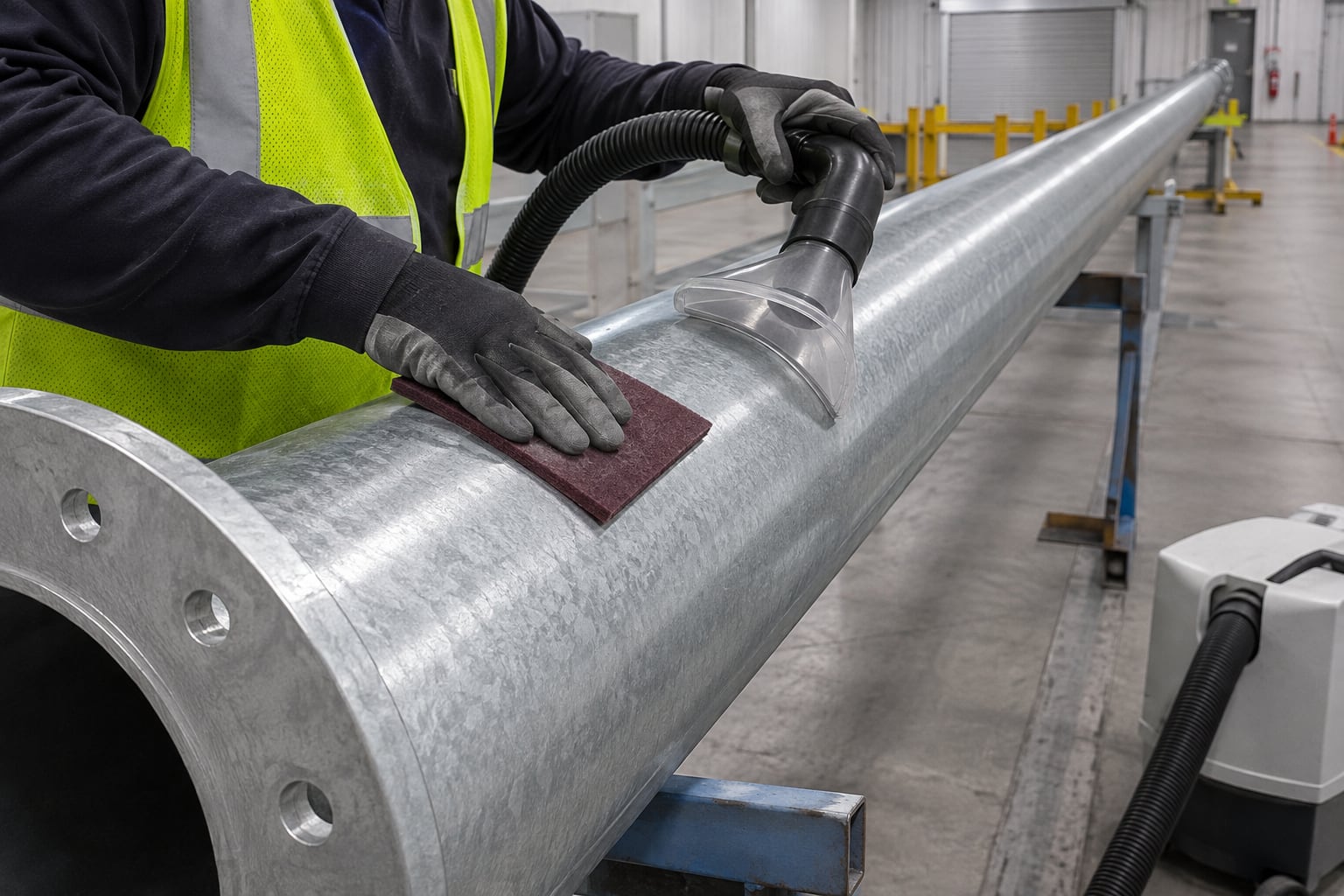
New galvanized surfaces may contain residues, storage contamination, moisture, zinc salts, runs or sharp projections that affect coating. Preparation should follow the selected coating supplier's guidance and the project specification. Cleaning, controlled abrasion or sweep treatment must create a suitable surface without aggressively cutting through the zinc layer. The correct method depends on surface condition and coating chemistry.
Timing also matters. A freshly galvanized pole that is kept dry and clean may require a different preparation sequence from one stored outdoors. Contaminated surfaces should not be coated merely to meet a color schedule. Record the condition, cleaning materials, preparation method and time between preparation and coating so the process remains traceable.
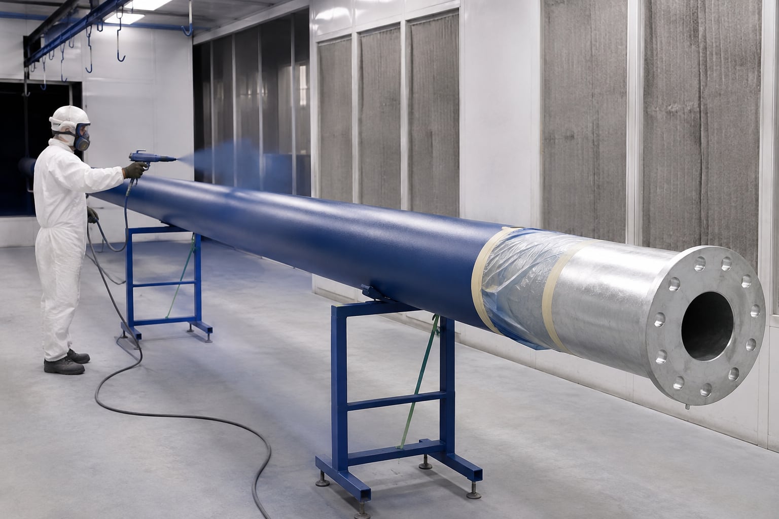
The pretreatment must be compatible with galvanized steel and with the selected organic coating. A project may specify a conversion treatment, primer, powder topcoat or a multi-layer liquid system. The required sequence should come from a defined system rather than combining unrelated products. Cure temperature and time must suit the pole geometry, zinc surface and coating manufacturer's documented process window.
Ask the supplier to identify the proposed product family and layer sequence in the quotation. If substitution is permitted, define the approval process and the evidence required to demonstrate compatibility. Color similarity alone does not make two systems equivalent. The final submittal should show how preparation, pretreatment, application, cure, inspection and repair work together.
State the color reference system and code, permitted tolerance, gloss range and whether a physical approved sample controls acceptance. Digital screens and printed pages can display color differently. If several suppliers provide luminaires, brackets or base covers, agree whether they must match exactly or only coordinate visually. Different materials and cure processes can create small appearance differences even with the same nominal code.
Dark and high-gloss colors may reveal handling marks, surface variation or field repairs more readily. Matte finishes can retain dirt differently. These are design and maintenance decisions rather than automatic quality rankings. A sample or first-article review can establish expectations before the full quantity is coated.
Not every surface should receive the same coating. Threads, electrical contact points, slip-fit zones, flange bearing faces, earthing studs and luminaire spigots may require masking or controlled thickness. Excess coating at a fit interface can prevent assembly; missing protection at an exposed edge can create a maintenance concern. The drawing and coating instruction should identify each exception.
Remove masking without tearing adjacent film, and protect exposed interfaces according to the approved assembly method. Fasteners should be selected and treated as part of the system. Do not assume that a painted nut, stainless fastener or galvanized bolt is automatically compatible in every coastal environment; the project engineer should review material pairing and isolation.
A thicker number is not automatically a better coating. Each layer has an intended range needed for coverage, cure, adhesion, flexibility and appearance. Excessive film can interfere with fit, create cure problems or mask surface features. Insufficient film can leave thin edges or reduced barrier performance. The project should specify the accepted system range and measurement method.
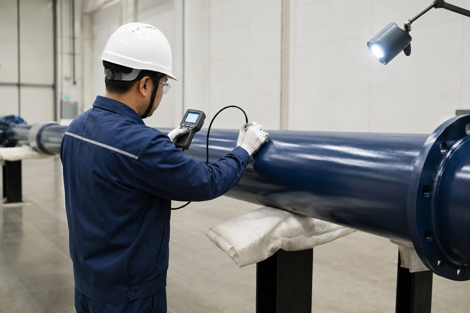
Measurements should be taken at representative locations using calibrated equipment and an agreed sampling plan. Complex geometry, edges and masked areas may need separate acceptance rules. Jieyao does not present one universal thickness for every coastal pole because steel geometry, coating product, exposure and specification vary. The approved order should record the values that apply to that project.
Agree which stages require inspection: fabricated steel, galvanized condition, preparation, ambient conditions, coating application, cure, final appearance, thickness, continuity, fit and packing. Record formats and hold points should be known before production. If the buyer needs witness points, define notice periods and the quantity or batch to be reviewed.
Useful records may include material traceability where specified, dimensional checks, galvanizing inspection, preparation confirmation, coating batch identification, cure logs, dry-film measurements, adhesion testing when required, color approval and packing photographs. The exact document set should reflect contract risk and specification; it should not be inflated with certificates that the project does not require.
If adhesion testing is required, identify the method, frequency, test location and acceptance criteria. Some methods can damage the tested area and therefore need a repair procedure. Do not request a generic “adhesion certificate” without defining what was tested. The same applies to holiday detection, impact, cure or salt-spray testing: state the relevant system and purpose.
Repair materials should be compatible with zinc and the organic layers. Factory repair, transport damage and field touch-up may use different methods because access and cure conditions differ. Define maximum repair size, preparation, layer sequence, color tolerance and inspection. A planned repair method is more useful than an unrealistic assumption that no coated item will ever be marked during a long logistics chain.
Finished color surfaces need soft, clean lifting slings and padded supports. Chains, bare steel forks and dirty webbing can cut or mark the coating. Lift points should keep the shaft stable without crushing thin local areas or contacting sharp edges. Operators should avoid dragging poles and should place them on supports that distribute load and keep coated surfaces above standing water or abrasive ground.
Handling instructions should travel with the shipment. They should cover unloading, stacking, sling selection, separation materials and inspection after movement. Small procedural improvements can prevent avoidable repair work. Structural components must also remain identifiable, so soft tags or protected labels should be used without scratching the finish.
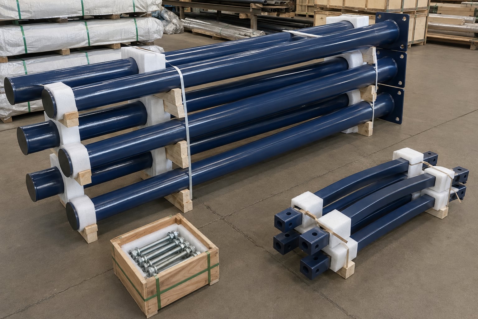
Separate coated shafts and arms with soft, non-staining pads. Protect base-plate edges, doors, spigots, flanges and contact points. Cap openings to limit contamination while allowing any required ventilation. Bundle geometry should suit the transport method without creating point loads that can dent the shaft or rub through the finish.
Anchor cages, bolts, nuts, washers and small brackets should be grouped by pole type and packed so threads remain protected. The packing list should connect each bundle with the drawing or pole schedule. For container shipments, confirm maximum section length, lifting access and unloading sequence before fabrication. Segmentation should be structurally designed rather than introduced only to fit a container.
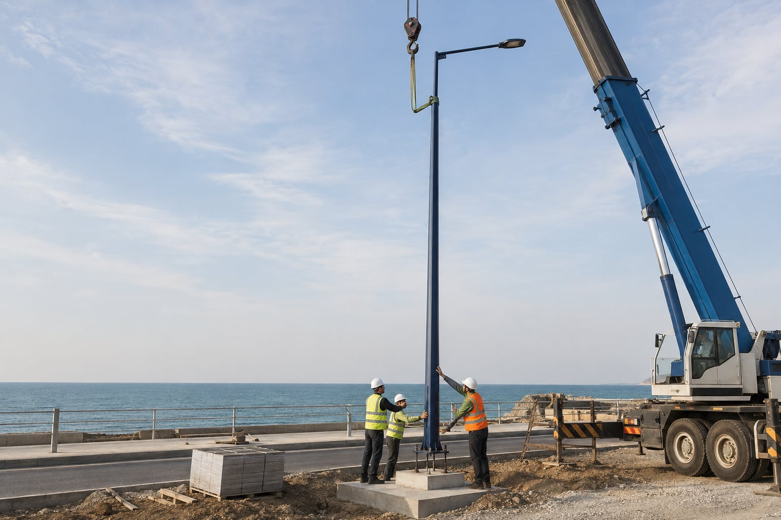
Inspect the foundation, anchor projection, bolt pattern and conduit position before the pole is lifted. Verify the pole mark, door orientation and arm direction. Use clean soft slings at approved positions and keep the shaft clear of crane hooks, chains and rough ground. Guide the base plate over the anchor bolts without scraping the coating across threads or concrete edges.
Level and tighten the assembly according to the approved structural method. Do not use impact or flame work near coated surfaces unless the design and repair procedure permit it. After erection, inspect the base, door, lifting points and arm connection in good light. Record and repair any damage before salt contamination becomes trapped beneath a temporary patch.
The repair method should match the damaged layers. A shallow mark in the organic finish may need a different treatment from damage that reaches zinc or exposed steel. Clean salts and contamination before repair, prepare the edges, restore the required layers and allow proper cure. Simply brushing a visually similar paint over an unprepared defect can trap contamination and make later inspection harder.
Keep the approved repair products, safety data and application instructions available to the installation team. Define who can authorize repairs and when a component must return for factory treatment. Photograph damage before and after repair where the quality plan requires it. Color variation in small field repairs should be addressed through an agreed acceptance standard rather than an improvised decision.
Plan how the owner will inspect the pole after commissioning. Accessible areas may include the base, anchor nuts, door perimeter, arm connection, fasteners, drainage paths and locations where attachments contact the shaft. Traffic control, climbing restrictions and luminaire access influence what can be inspected economically. These constraints should be considered before choosing decorative covers or concealed connections.
Maintenance frequency is site specific. A practical program may combine cleaning, visual inspection, repair of mechanical damage and closer review of high-risk details. Records help identify recurring problems such as water retention, incompatible hardware or handling damage. The page does not promise a fixed service life because exposure, design, application quality, damage and maintenance all influence actual performance.
Two quotations can both say “galvanized and powder coated” while including very different preparation, layer sequence, inspection and packing. Build a comparison sheet with columns for galvanizing standard, zinc acceptance, post-galvanizing preparation, pretreatment, coating product family, number of layers, thickness range, color, gloss, cure control, inspection, repair and packing. Mark every exception.
Also compare the structural scope: steel grade, shaft sections, arms, openings, door, base plate, anchors, luminaire interface, design inputs and drawings. A low coating price can be misleading if the pole configuration or inspection package is incomplete. Technical equalization should occur before commercial selection so suppliers are pricing the same deliverable.
Request a scope statement, preliminary arrangement, material proposal, coating data, list of standards, deviations, inspection plan and packing concept. The arrangement should show height reference, arm reach, luminaire interface, door orientation, base dimensions and anchor pattern. The coating proposal should identify the zinc and organic layers separately and state which surfaces or parts are excluded.
After order, agree the drawing and submittal schedule. Documents may include fabrication drawings, anchor template, coating procedure, color sample, inspection records, packing list and installation guidance. The purchaser should state required languages, file formats, approval status and response times. Clear document control prevents an approved color or anchor revision from being lost between procurement and production.
Use the coating intent together with the correct height and layout page. An 8 m galvanized street light pole may suit urban coastal streets when the photometric design supports that height. Taller open roads may require the 12 m highway street light pole or another project-specific structure. The coating system can be specified on the selected structural arrangement.
Do not choose height from a product name alone. Road width, setback, luminaire distribution, mounting height, maintenance access, wind demand and foundation constraints all matter. Jieyao can review the schedule as a family so repeated shaft, arm, base and color requirements are controlled while each pole type keeps its correct loads and orientation.
One coordinated package gives the fabricator, galvanizer, coating applicator and inspector a shared drawing and acceptance basis. Welds, drains, doors, masks, fit interfaces and handling points can be reviewed before work starts. It also makes responsibility for factory repair and packing clearer. The result is not a universal guarantee; it is a more traceable supply scope.
Jieyao can prepare a project-specific proposal using the buyer's exposure assessment, pole schedule, luminaire data, structural criteria and coating specification. The proposal can distinguish included items, optional items and purchaser responsibilities. This supports technical equalization and reduces assumptions before drawings and production are released.
It is a galvanized steel pole with a compatible organic coating system applied over the prepared zinc surface.
No. A duplex system includes the galvanized zinc layer and the compatible organic layer as one defined system.
Yes. State the color reference, gloss, tolerance and whether an approved physical sample controls acceptance.
No. Exposure, maintenance, geometry and the governing project specification determine the required system.
Yes. Provide the lighting layout, equipment data, clearances and structural design basis.
Provide shore distance, wind direction, splash, humidity, deposits, cleaning plan and site photographs.
Their geometry, sealing, drainage, masking and coating scope are defined on the approved drawing.
Yes. The bolt pattern, projection, material and protection must match the selected base and foundation design.
Use soft separators, protected contact points, capped openings, stable cradles and identified hardware packs.
Often yes, using the approved preparation and layer sequence within the agreed repair limits.
The order can define dimensional, galvanizing, preparation, coating, cure, thickness, color and packing records.
Include exposure, pole schedule, luminaires, wind basis, coating system, interfaces, records and logistics.
Send your site description, road layout, pole schedule, luminaire data, structural criteria, color reference and coating specification. If some inputs are still under development, mark them clearly so the quotation can separate assumptions from confirmed requirements. Photos, tender clauses and a typical pole elevation are useful starting documents.
Jieyao can coordinate pole geometry, galvanizing, compatible color coating, bases, anchors, drawings, inspection and export packing around one documented project scope.
Request a Coastal Lighting Pole Review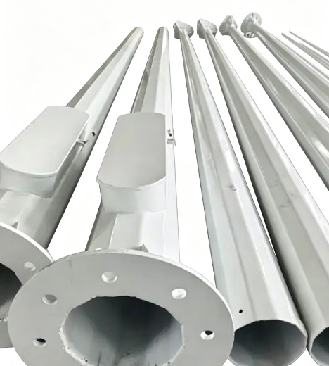
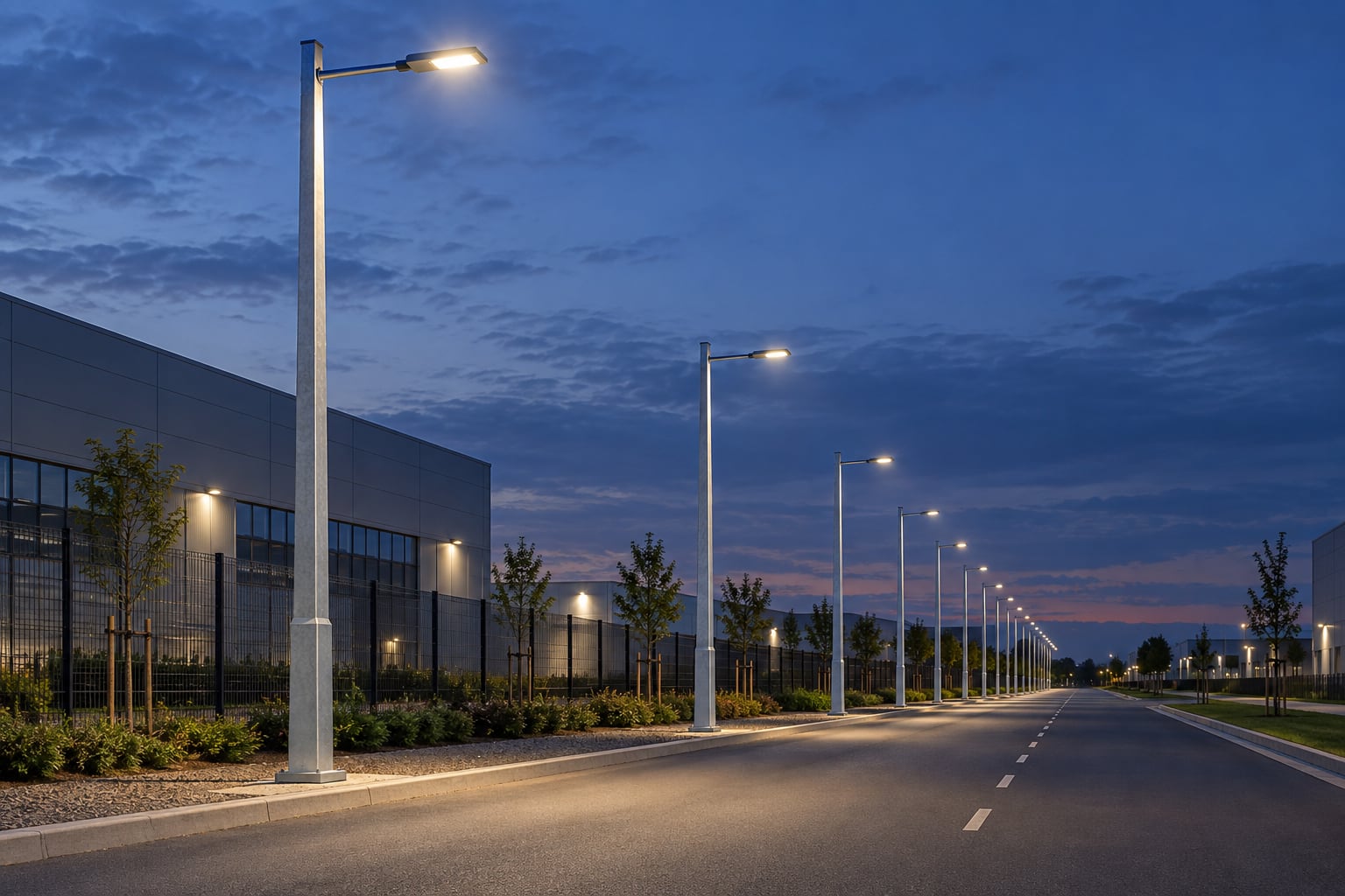
Plan a parking lot light pole layout with photometric files, protected pole locations, glare control, structural loads, foundations and maintenance access. Height and spacing are project-specific.
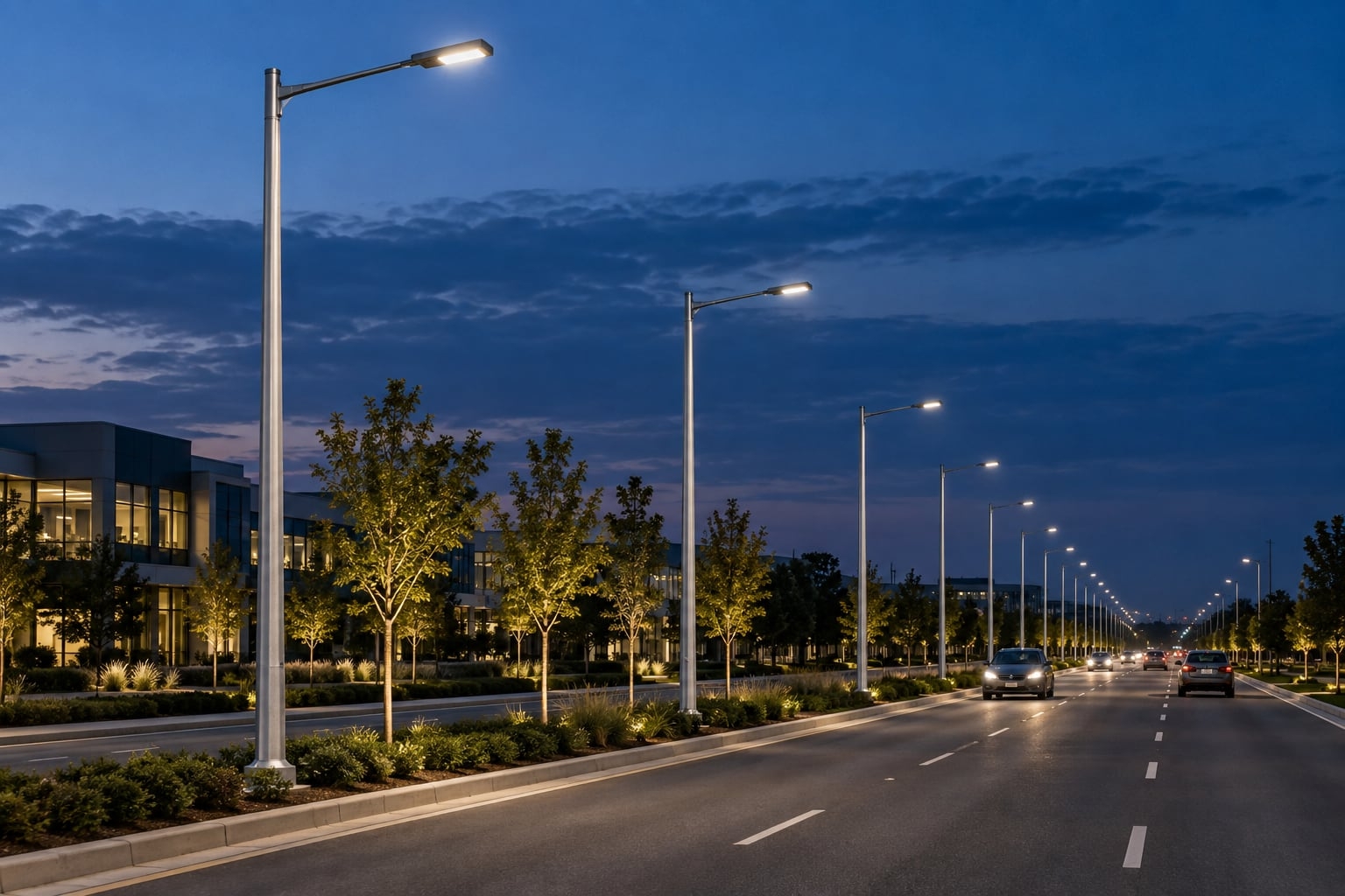
Learn how to choose lighting poles for airports and ports. Understand key selection standards including wind load resistance, corrosion protection, pole height, material choice, and safety requirements for aviation and marine environments.
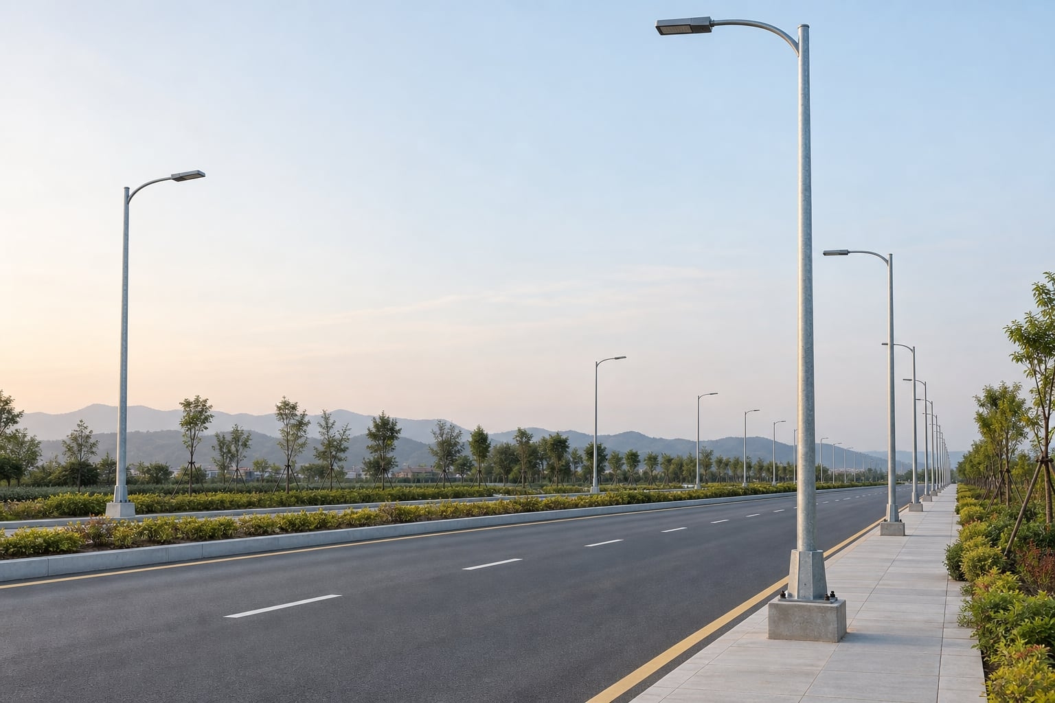
Compare hot-dip galvanizing, direct-to-steel paint and compatible duplex coatings for street light poles by exposure, detailing, inspection and repair scope.
Compare galvanized steel, aluminum and stainless steel light pole assemblies by structural design, fabrication, corrosion control, finish, handling and inspection evidence. Select materials for the project exposure and approved supply scope.
Compare single arm and double arm street light poles for roads, highways, parking areas, and municipal projects. Learn the differences in lighting coverage, installation cost, application scenarios, and how to choose the right street light pole for long-term project performance.
The best pole for solar street lights depends on wind load, environment, and project scale. Learn when to choose steel, aluminum, or galvanized steel poles for different outdoor lighting applications.
Discover the life expectancy of street light poles based on materials like steel, aluminum, and concrete. Learn how climate, installation quality, and maintenance affect pole lifespan in real outdoor lighting projects.
Learn how to install a solar street light with pole step by step, including foundation construction, pole erection, wiring, and system testing. A practical guide for road lighting, parking lots, and outdoor solar lighting projects.
We primarily use high-strength carbon steel (Q235/Q345/ASTM A36). We also offer premium aluminum alloy and stainless steel poles specifically for coastal regions.
Tapered poles are aesthetic with low wind resistance; cylindrical poles are more cost-effective; polygonal poles (usually 8/12/16 sides) offer the highest structural strength, ideal for high mast lighting.
Our engineers perform mechanical calculations based on your local wind speed data, adjusting wall thickness and base design to ensure the poles can withstand winds up to 160km/h.
It typically ranges from 3mm to 12mm, depending on the pole height, weight of the fixtures, and local wind load requirements.
This is an anti-corrosion process of immersing steel in molten zinc. It provides over 25 years of maintenance-free rust protection in standard outdoor environments.
Yes. We provide complimentary foundation reference drawings, including concrete depth, rebar specs, and bolt positioning data.
We follow AWS welding standards and use Ultrasonic Testing (UT) or Magnetic Particle Testing (MT) to ensure welds are free of pores or cracks.
We hold ISO 9001 (Quality), ISO 14001 (Environmental), and CE certification (EN 40) specifically for the European market.
Yes. We can produce sample poles for craft and color confirmation, though sample shipping costs are typically covered by the client.
Steel poles are lighter, easier to transport and install, have a long lifespan after galvanization, and offer high scrap value, making them more eco-friendly.
Galvanized poles are virtually maintenance-free. We recommend checking anchor bolt tightness and the powder coating surface every 3-5 years.
We provide touch-up paint with each shipment. Simply clean the scratch and apply the paint to restore the appearance.
No. Base plate size and hole spacing are designed based on pole height and stress loads. We provide detailed dimensional drawings for each order.
These are accessories (like anti-climb spikes) installed on the lower section of the pole to prevent unauthorized climbing and enhance security.
Yes. We can flexibly adjust section lengths (e.g., 6m+6m or 5m+7m) based on logistics constraints and on-site installation conditions.
Contact Us
Get a custom lighting solution and quotation for your project. Outdoor lighting manufacturer in Yangzhou, ChinaAbout Jieyao LightingYangzhou Jieyao Lighting Equipment Co., Ltd. is an outdoor lighting manufacturer focused on solar street light systems and high mas... Do you have any questions or requests?
Email: jay@jieyaolighting.com

Click to Chat.
Im online now.