

A practical guide to coordinating pole reactions, base plates, anchor-bolt cages, conduits, reinforcement, concrete work, erection checks and the documents that keep the lighting and civil packages aligned.
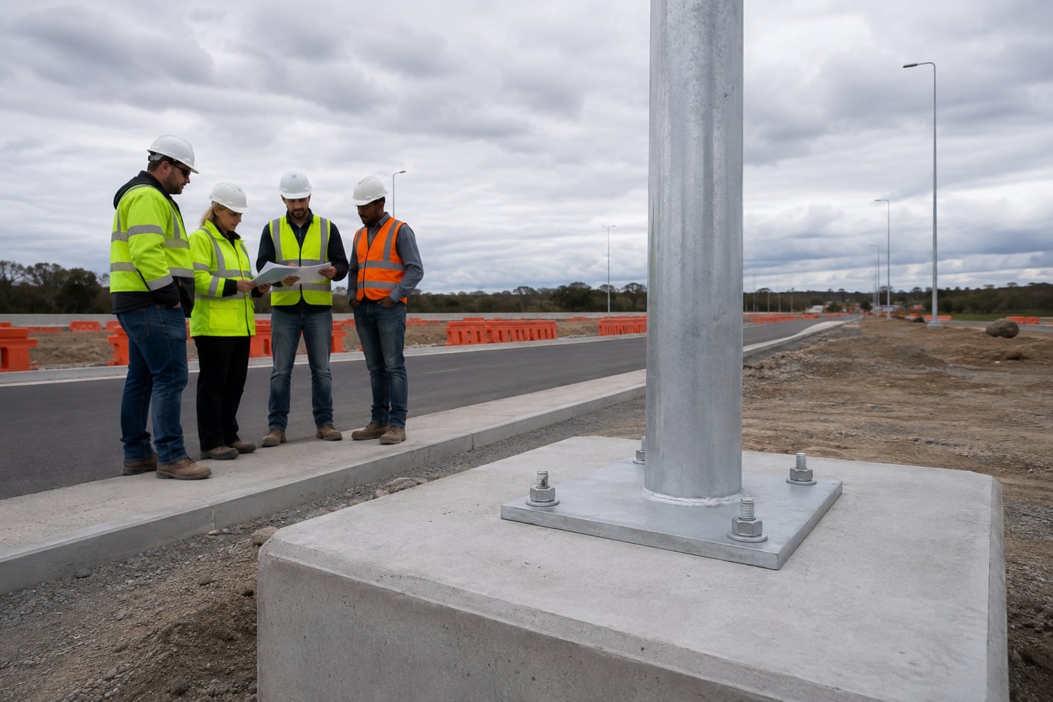
A street light pole foundation transfers actions from the luminaire, bracket and shaft into the ground. Wind on the pole and fixture creates bending and shear; equipment weight adds axial load; an offset arm or accessory can add torsion. The base plate, anchor bolts, reinforcement, concrete and surrounding soil must carry these actions as one continuous load path.
That is why a catalogue foundation size is rarely a complete answer. Two poles of the same height can have different top dimensions, wall schedules, arm reaches, luminaires, wind exposure and base reactions. Soil resistance, groundwater and roadside geometry can also differ. The final foundation should be designed or verified for the approved pole configuration and actual site.
Provides the approved pole arrangement, base plate and anchor details, and the design reactions or calculation scope agreed for the supplied configuration.
Uses geotechnical data, local code, drainage and site constraints to design or verify the concrete foundation, reinforcement and ground interface.
Defines conduits, cable routes, earthing, equipment space and separation requirements that pass through or beside the structural assembly.
Confirms excavation access, temporary works, cage positioning, concrete placement, curing, lifting, alignment and as-built records.
Fixes mounting height, arm direction, fixture model and accessories so the structural load basis matches the photometric layout.
Controls document revisions and makes sure supplier assumptions, civil drawings and field work describe the same interface.
| Interface | Required evidence | Release owner |
|---|---|---|
| Pole and lighting | Pole mark, height, arm, fixture/accessory loads and approved wind basis | Lighting/structural reviewers freeze the configuration |
| Steel base | Reactions, plate, holes, anchors, orientation and support condition | Pole supplier releases the exact interface revision |
| Civil foundation | Soil/groundwater data, concrete/reinforcement design, drainage and clearances | Responsible civil designer accepts the site-specific foundation |
| Electrical and construction | Conduit/earthing plan, set-out, temporary bracing and inspection records | Electrical/site quality teams release the pre-pour hold point |
Foundation work should not start from pole height alone. The civil designer needs the pole reactions, base and anchor drawing, governing load combinations and support assumptions. Site inputs normally include soil profile and resistance parameters, groundwater, frost depth where relevant, slope, fill condition, nearby utilities, pavement or barrier geometry and required finished level.
The pole data should identify luminaire mass and exposed area, arm geometry, accessories and the wind basis used. If these are preliminary, the drawing should state the assumed envelope. Production, foundation construction and equipment procurement should converge on one approved revision before irreversible work begins.
Project location data should be specific enough to connect each reaction set to each foundation type. A schedule may contain roadside single-arm poles, median double-arm poles, taller junction poles and shorter pedestrian units. Giving every item the same civil detail for convenience can hide meaningful load differences. Item marks and a foundation-type matrix make the relationship visible to procurement and construction teams.
Reactions describe how the approved pole configuration loads its support. Axial force may include dead load and wind-related uplift or compression. Horizontal shear follows wind direction and other lateral actions. Overturning moment is commonly critical for a tall pole, while torsion may become important with long, unequal or multi-directional arms.
The reaction sheet should identify units, coordinate axes, load combinations and whether values are characteristic, factored or otherwise defined by the governing method. A foundation engineer cannot safely combine numbers whose basis is unclear. The pole supplier and civil designer should also agree on the elevation at which reactions are reported.
A fixed statement such as “use a foundation one meter wide and two meters deep” ignores too many variables. Soft clay, dense sand, rock, uncontrolled fill and high groundwater provide different resistance. A sheltered local road and an exposed coastal highway can impose different actions. Frost, scour, slope and utility trenches may further change the design.
Even when two sites use the same pole, construction methods can differ. A drilled shaft, cast rectangular footing, pedestal on a larger base or bridge-mounted connection has a different load path. Reference dimensions may help early budgeting, but they should be labeled preliminary and checked by the responsible local engineer.
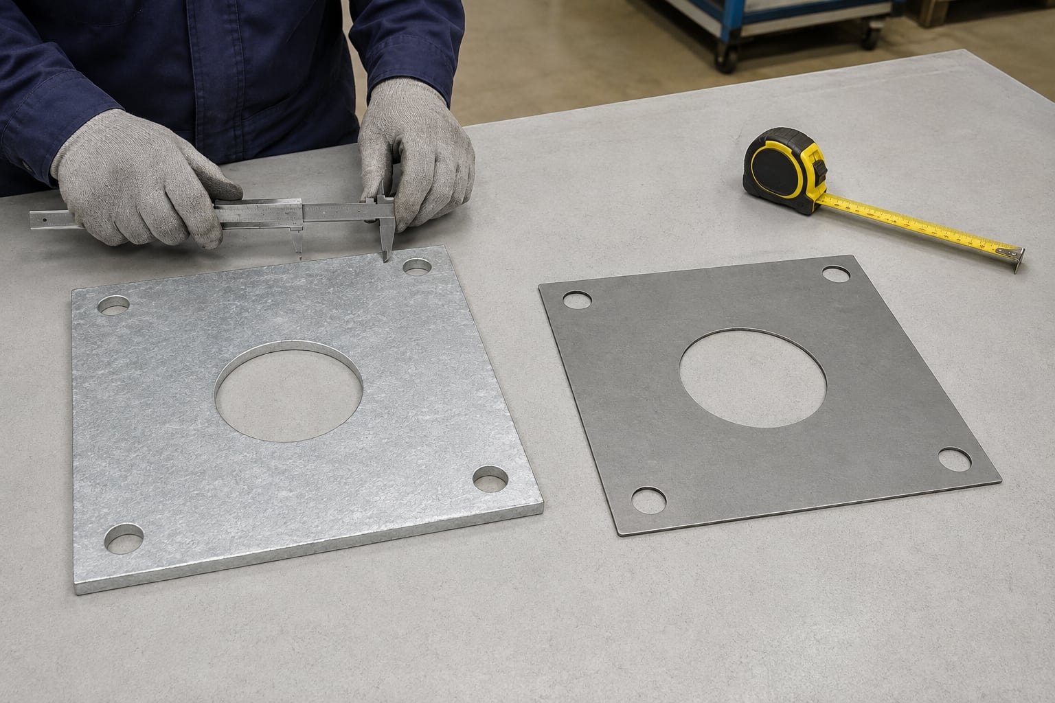
The base plate drawing links the fabricated pole to the anchors and concrete. It should show outside dimensions, thickness, bolt-hole diameter and circle or coordinates, central cable opening, shaft position, stiffeners where used, weld detail and orientation of the access door and arm. Clearances must allow nuts, washers, tools and cable installation.
The drawing should also state the intended bearing or leveling condition. Changing the gap beneath the plate, adding washers not shown or enlarging holes on site can alter local behavior. If the civil drawing uses a different bolt circle or finished level, the conflict should be resolved before reinforcement is fabricated.
Base orientation can be dimensioned from the access door, shaft seam, arm centerline or a project north arrow. The chosen reference must be unambiguous. Symmetrical plate outlines can still contain asymmetric stiffeners or cable openings, so installers should not assume that any ninety-degree rotation is acceptable.
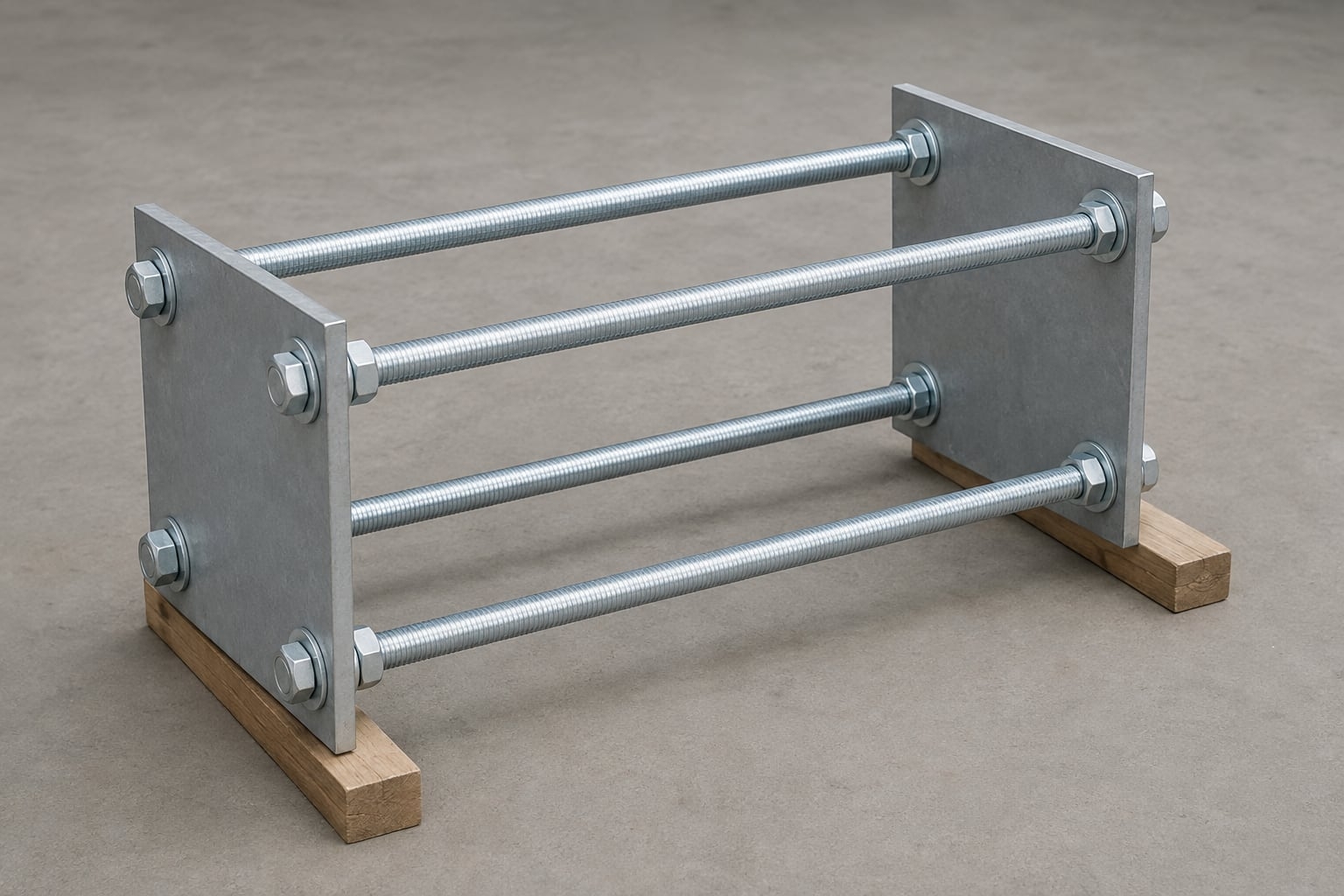
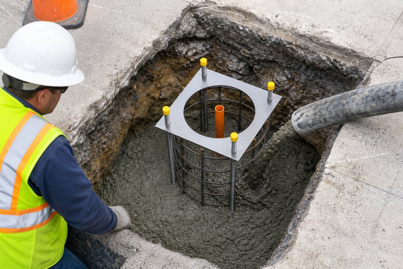
A typical cage can include anchor rods or bolts, one or more templates, nuts, washers and connection or support pieces. The arrangement holds bolt spacing during transport, reinforcement work and concrete placement. Bolt material, diameter, thread, length, bend or anchorage detail and supplied finish follow the project design.
Templates control geometry but are not automatically permanent structural plates. The drawing should identify whether a template is removed, left in place or used only during assembly. Loose hardware should be counted and protected. Item marks help installers match cages to poles when several base patterns share one project.
Transport supports are also part of practical cage quality. Long rods can bend if a cage is lifted from one corner or stacked under uneven loads. A preassembled cage should arrive with the template spacing, diagonals and thread condition intact; otherwise it needs inspection and an approved correction before being placed in reinforcement.
The bolt pattern must match the base plate within the permitted tolerance. A rigid template helps maintain the circle or rectangular coordinates, but the entire cage still needs bracing so it cannot rotate, tilt or rise during the pour. Measurements should be taken between centers and across diagonals rather than from an irregular excavation edge.
Orientation matters when the base is not rotationally symmetrical or when door and arm directions are fixed. Survey control should relate the template to the road centerline or project grid. A simple orientation mark on the cage, pole and drawing can prevent a correct pattern from being installed at the wrong angle.
Anchor material and mechanical properties should match the approved structural specification. Thread form, nut grade, washers and protective finish must be compatible. Mixing components without review can create fit or capacity problems. Threaded portions should be protected from impact, contamination and concrete during storage and placement.
Projection above finished concrete is controlled by the base plate thickness, intended leveling or bearing arrangement, washers, nuts and required thread engagement. Too little projection prevents full assembly; excessive projection can interfere with covers or leave long exposed threads. The cage drawing should dimension projection from a defined finished elevation.
Anchor capacity depends on more than overall bolt length. The design may need to consider steel strength, concrete breakout, pullout, side-face effects, edge distance, spacing, reinforcement interaction and the way force is transferred at the embedded end. Bent, headed, plate-anchored or other details should not be substituted without engineering review.
The cage must fit within the concrete and reinforcement while maintaining cover and construction tolerance. If the permitted foundation envelope is small, the civil and pole designs may need to be coordinated rather than forcing an oversized anchor pattern into congested reinforcement.
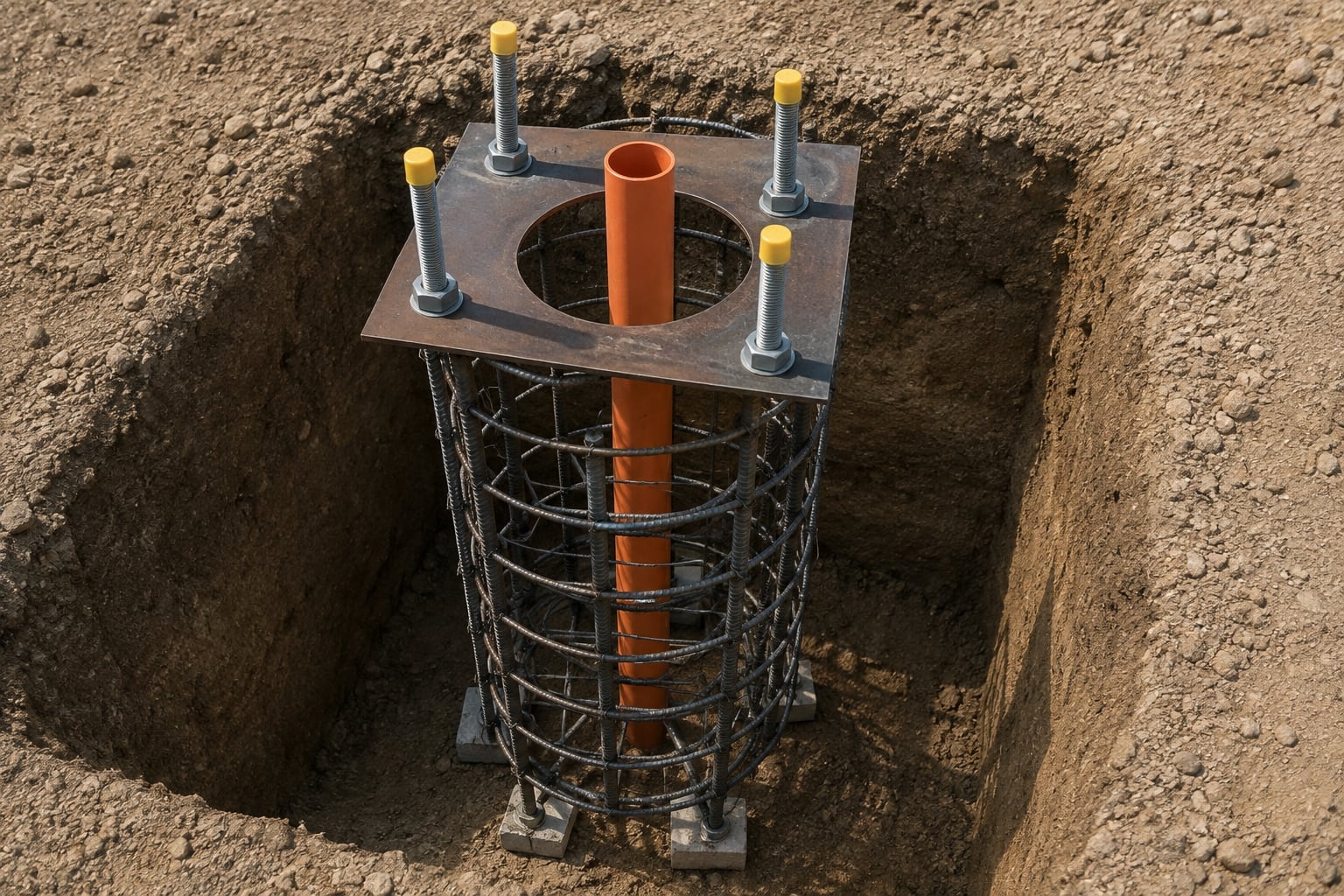
Longitudinal bars, ties or spirals and local reinforcement should be detailed around the anchor system. Bars cannot occupy the same space as anchor rods, nuts, plates or conduits. Congestion also needs enough room for concrete to flow and be consolidated. Moving reinforcement in the field without approval can change the intended foundation behavior.
A combined section drawing is more useful than separate sketches that never show overlap. It should include concrete cover, cage dimensions, bolt projection, template elevation, conduit route and any pedestal transition. Where prefabricated cages are used, lifting points and temporary supports should prevent distortion.
The electrical conduit normally rises through a central base opening or another defined path. It must not collide with anchors, reinforcement, stiffeners or the pole shaft. The bend radius and pulling route should suit the cable, and the top elevation should allow the pole to seat as designed.
Multiple circuits, spare ducts or communication cables increase congestion. The electrical and civil drawings should use the same coordinate system and finished level. A conduit placed after the cage is tied can push the anchor pattern off center, so its route should be checked before the pour.
Conduit ends should be capped during concrete work, and pulling provisions should remain usable. The route outside the footing also needs adequate cover and separation from drainage or other services. A correctly centered riser is of little value if an abrupt bend below the foundation prevents cable installation.
Earthing requirements depend on the electrical design and local rules. The pole may include an internal earthing lug, while the civil and electrical scope may include electrodes, conductors or bonding to reinforcement. The connection must remain accessible enough to install and test without drilling the galvanized shaft.
The drawings should identify who supplies each component and where the conductor enters the pole. Corrosion compatibility, mechanical protection and separation from power circuits should be considered. A foundation image cannot establish a compliant earthing system; the project electrical specification remains controlling.
Soil information helps the engineer evaluate bearing, lateral resistance, uplift, settlement and construction stability. Useful data may include strata, density or strength parameters, groundwater level, fill history and recommendations for excavation or drilled construction. Conditions can vary along a long road, especially near culverts, embankments and reclaimed ground.
Groundwater can affect excavation safety, concrete placement, buoyancy, corrosion exposure and drainage. If water is encountered at a different level from the report, work should follow the project's change and inspection process rather than continuing with an unverified assumption.
Cold-region foundations may need frost-depth and heave considerations. Sloping shoulders can reduce soil cover on one side and complicate finished pedestal height. Concentrated runoff, ditch flow or floodwater can erode support or leave water around the pole base. These site effects should appear in the civil design.
The installed base should shed water and remain inspectable. Burying the base plate in soil or creating a pocket that holds salts and water can accelerate corrosion. Landscape, paving and future resurfacing levels should be coordinated so maintenance access is not lost.
Roadside foundations may sit near barriers, slopes, drains and utilities. Median locations can have narrow working space and strict traffic-control requirements. Bridge or retaining-structure mounts introduce a different support system, with reinforcement, deck waterproofing, fatigue and edge-distance constraints that do not match a ground footing.
The foundation designer should also check clear-zone, setback and breakaway requirements where applicable. A standard fixed base may not be suitable for every authority or speed environment. Pole selection and civil support should be coordinated with the road-safety design.
Matching the old bolt pattern does not prove that an existing foundation can support a new pole. The survey should record bolt coordinates, diameter, projection, corrosion and thread condition, pedestal dimensions, cracking, tilt, cable path and surrounding ground. Available drawings and the original load basis should be reviewed.
A qualified engineer should evaluate the existing foundation against the new reactions and current project requirements. The new base plate may need a designed adaptor, but drilling, welding or enlarging holes in the field should not be assumed acceptable. Unknown embedment or damaged concrete can make replacement the more reliable option.
Before excavation, the contractor should follow the project's utility-location and permit procedures. Lighting cables, drainage, communications, gas, water and road-control systems may share a narrow corridor. The foundation must fit without damaging existing services or reducing required clearance.
Excavation support, access and spoil control depend on depth, soil and traffic conditions. Workers should not enter an unsupported excavation. If an obstruction forces the foundation to move, the lighting layout, cable route and civil design may all require revision; shifting only the hole can reduce photometric performance or create a base mismatch.
Before concrete, verify cage identity, reinforcement size and spacing, concrete cover, anchor pattern, diagonals, projection, verticality, template level, orientation, conduit position and earthing provisions. Temporary supports should hold the assembly against movement from workers, hose pressure and vibration.
Photographs and survey records are valuable because most details become hidden. The inspection should reference the latest approved drawings. A clean pre-pour hold point is usually easier and less expensive than correcting misplaced anchors after concrete has hardened.
Tolerances should be stated before inspection. The team needs to know acceptable pattern, projection, level and verticality limits and who can accept a deviation. A template that appears visually square may still be outside the base-plate allowance, so calibrated measurement and diagonal checks are more reliable than appearance alone.
| Check group | Field verification | Record or response |
|---|---|---|
| Location and level | Centerline, finished level, orientation and clearance to roads/utilities | Survey record tied to the foundation and pole mark |
| Anchors and template | Count, pattern, diagonals, projection, verticality, thread protection and bracing | Measured values; resolve deviations before concrete |
| Reinforcement and conduit | Bar/cage identity, cover, anchor clearance, conduit position and earthing route | Checklist and photographs before details become hidden |
| Document control | Current approved pole/base, civil and electrical revisions | Named inspector signs the hold-point release |
Concrete placement should follow the approved mix, method and quality plan. Delivery and consolidation must fill around reinforcement and anchors without segregating material or shifting the cage. Anchor threads and conduit openings should remain protected. The top elevation and finish should match the bearing or grout detail.
Required sampling, testing, curing and release strength are project-specific. The pole should not be erected merely because the surface looks hard. The responsible engineer or specification should define when the foundation can receive installation loads.
Projects use different approved base-support details. A plate may bear on a prepared surface, use designed leveling nuts, approved shims or a specified non-shrink grout system. The selected detail affects load transfer, drainage, nut arrangement and installation tolerance. It must be shown rather than improvised.
Large unsupported gaps, stacked random washers or incomplete grout can create uneven bearing and water traps. Grout preparation, placement and curing should follow its specification. Weep or drainage details, if required, must remain open without compromising support.
Before lifting, compare the pole item mark with the foundation and verify anchor spacing, projection, conduit, concrete release and access. The lifting plan should use suitable equipment, competent personnel and an exclusion zone. Cables need protection while the shaft is lowered over the anchors.
Door and arm orientation should be checked before the pole is seated. A pole can fit a symmetrical four-bolt pattern while facing the wrong direction. Survey marks and a clear orientation diagram reduce rework, especially for median double-arm poles and intersection equipment.
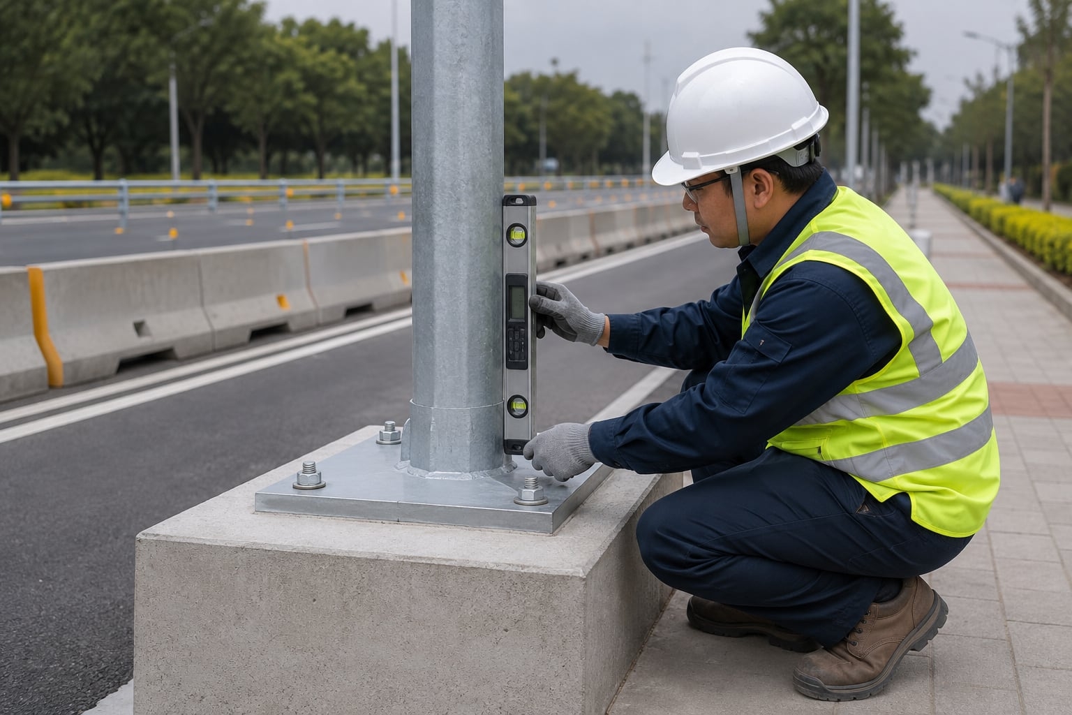
Plumb is checked using an appropriate method and at a time when wind or temporary loading will not distort the reading. Adjustment follows the approved base detail. Final nut tightening or preload, where specified, requires the defined procedure, tools and sequence rather than a universal torque value.
Inspection should confirm seated washers, thread engagement, base support, grout condition, cover fit, cable protection, door orientation and coating damage. Any nonconformance should be recorded and resolved before the luminaire or accessories add further load.
After the first installation, a short feedback loop can improve the remaining foundations. If installers find limited wrench clearance, unexpected conduit height or difficult door orientation, the project team can compare the issue with the approved detail before repeating it along the route. Any revision must still be formally controlled.
The pole, base plate, anchors, nuts and washers need a compatible protection plan for the environment. Galvanizing, coatings and repair materials should match the specification. Handling damage, cut threads and field modifications require an approved repair method.
Base geometry should avoid retained water, soil contact and pockets of deicing salt. Coastal or industrial sites may justify additional protection and more frequent inspection. See the coastal duplex-coated lighting pole for a product-level coating coordination approach.
A traceable record set can include approved pole and civil drawings, reaction sheet, geotechnical reference, cage inspection, concrete delivery and test records, survey data, curing release, erection checklist and final photographs. The required package depends on contract scope and authority rules.
As-built anchor and conduit information is particularly useful for replacement work. Records should identify pole or foundation locations rather than rely on generic batch photographs. Revision control prevents a valid record for one base type from being applied to another.
A footing from another site is used without comparing reactions, soil, groundwater or code.
The base plate and civil drawing use different circles, hole diameters or orientations.
Ducts cross anchors or rebar and prevent the pole from seating or cables from turning.
Bolt projection is measured from excavation or formwork rather than the defined concrete top.
Concrete placement tilts or rotates an inadequately braced template.
Slots, bends, welding or plate changes are made to force a connection after the pour.
Confirm whether the pole quotation includes the base plate, anchor cage, template, nuts, washers, reactions, drawings and any structural calculation. Check material, finish, quantities and document timing. An inexpensive offer may omit anchors or assume a foundation pattern that is not compatible with the civil package.
Also define the responsibility boundary: pole reactions and anchor supply do not automatically include site-specific concrete design. Compare suppliers using the same wind and equipment basis. The wind-load and EPA RFQ checklist helps normalize structural inputs for taller systems.
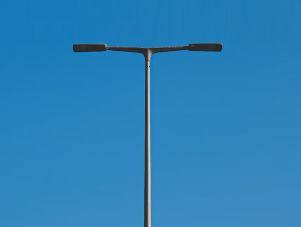
Foundation demand follows the complete pole configuration. A 10m single-arm street light pole and a 10m double-arm pole can require different reactions even at the same height. The 12m highway pole adds tall-roadway transport and wind considerations.
Traffic signal supports carry different mast-arm and signal equipment loads; see the standard traffic signal pole. The broad street light pole range helps identify shaft and mounting options before requesting a project-specific foundation interface.
A qualified project civil engineer should design or verify it using pole reactions and site data.
No universal size fits every pole, wind condition, soil profile and construction method.
Provide the defined axial, shear, moment and torsion actions with units and load basis.
Site-specific geotechnical information is important for reliable foundation verification.
Yes, when their material, geometry, templates, nuts, washers and finish are agreed.
Only after its geometry, condition and capacity are checked against the new pole reactions.
Projection follows the approved plate, leveling, washer, nut and thread-engagement detail.
Use the defined base opening while keeping clear of anchors, reinforcement and stiffeners.
No. Use the specific bearing, leveling and grout arrangement shown by the project design.
Drainage, salt exposure, compatible protection and inspection frequency need added attention.
After the concrete meets the release condition defined by the responsible specification or engineer.
Include pole reactions, base and anchor details, civil design, conduit, orientation and revision status.
Send the pole schedule, luminaire and arm data, wind criteria, base constraints, geotechnical information, conduit plan and required documents. Jieyao can coordinate the pole base, anchor cage and reaction package for review by the project civil engineer.
Contact Us
Get a custom lighting solution and quotation for your project. Outdoor lighting manufacturer in Yangzhou, ChinaAbout Jieyao LightingYangzhou Jieyao Lighting Equipment Co., Ltd. is an outdoor lighting manufacturer focused on solar street light systems and high mas... Do you have any questions or requests?
Email: jay@jieyaolighting.com

Click to Chat.
Im online now.