Parking Lot Light Pole Product Overview
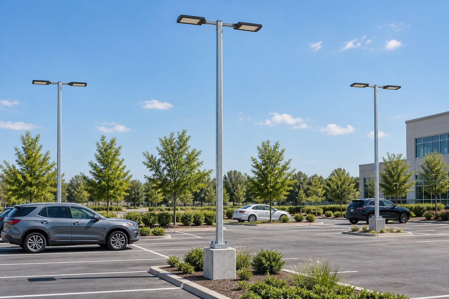
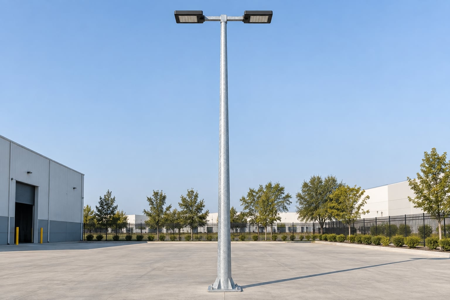
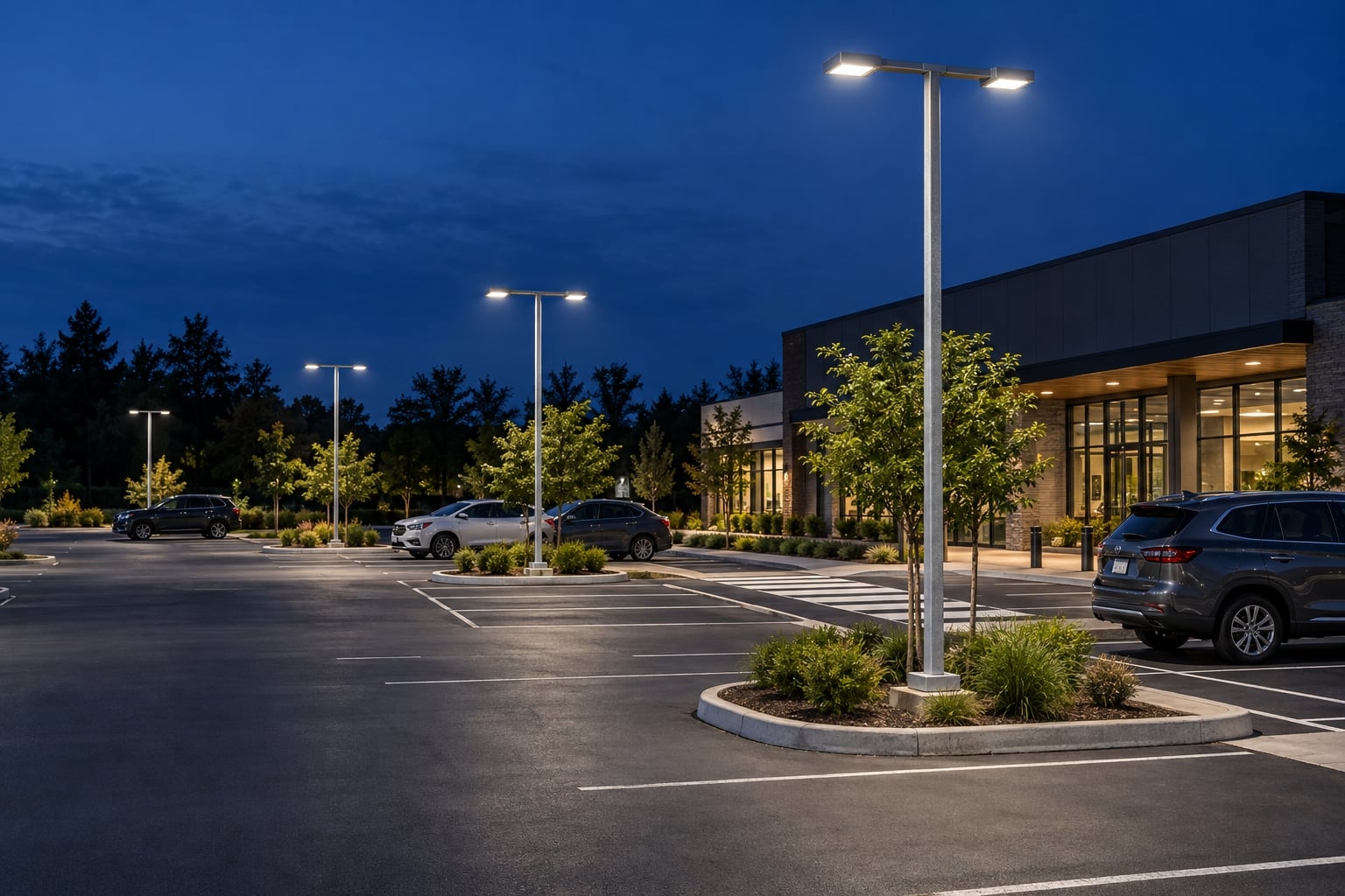
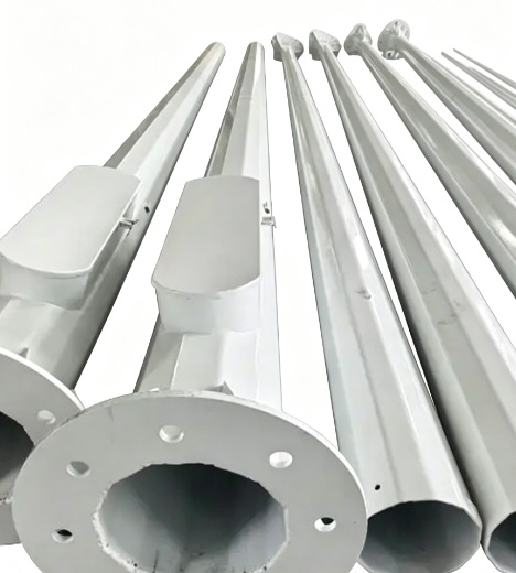
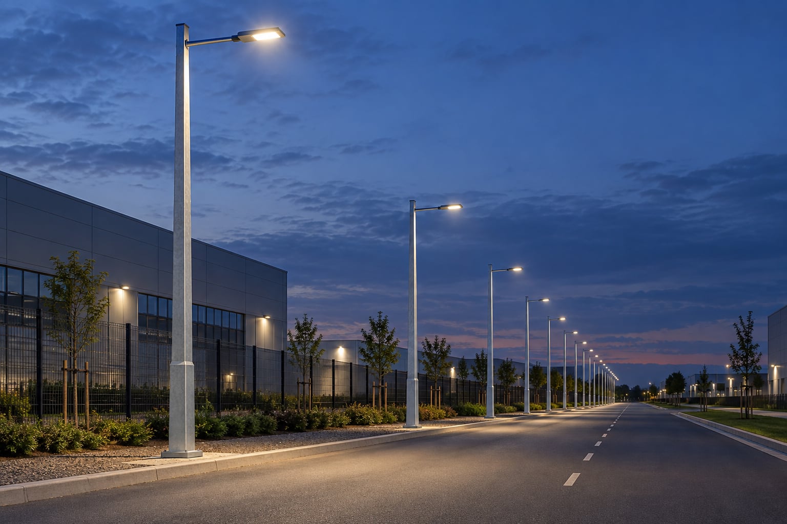
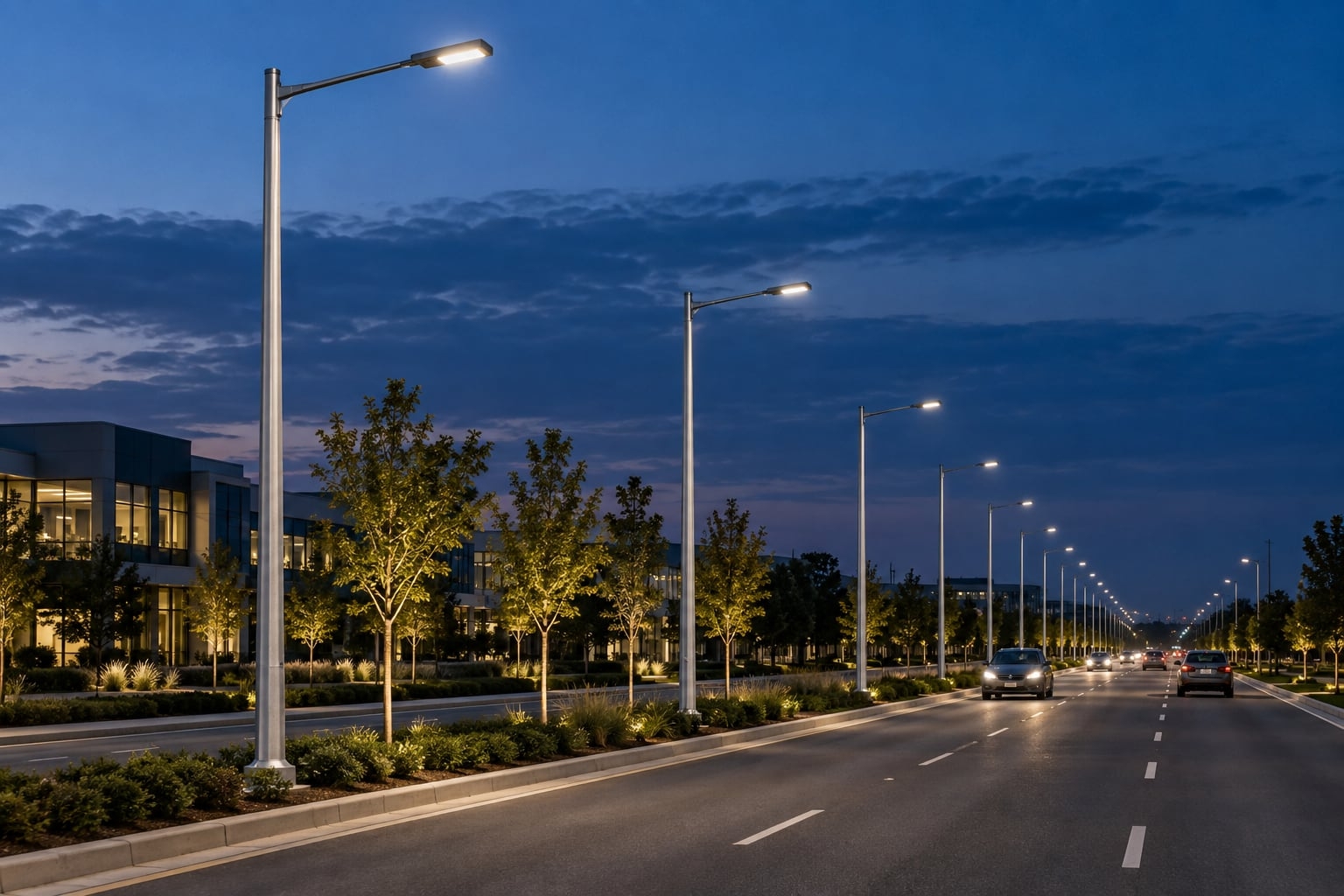
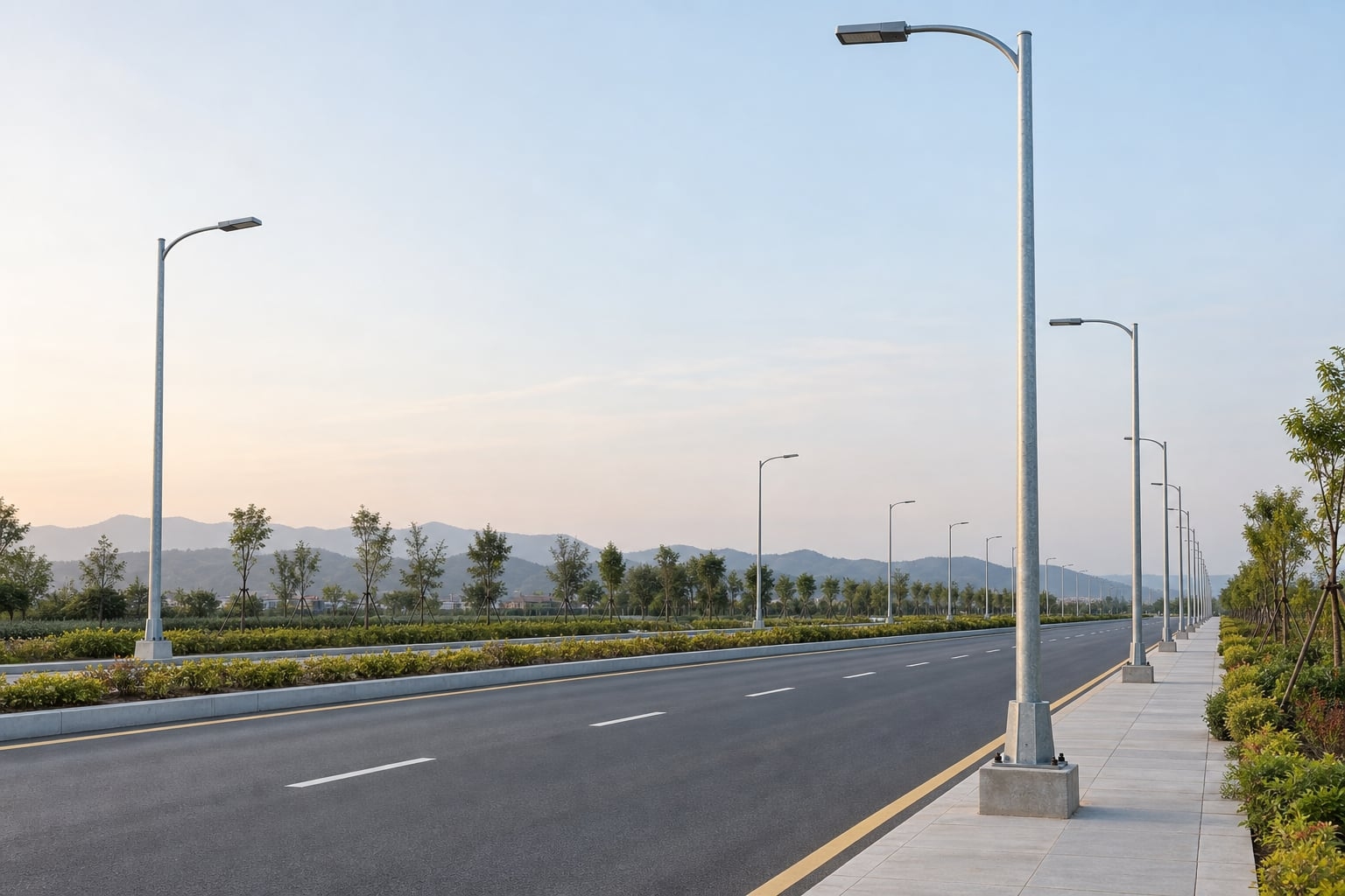
A galvanized steel parking lot light pole supports one or more LED area luminaires above parking bays, access aisles, pedestrian routes and building approaches. Unlike a roadway pole that mainly follows a linear carriageway, a parking-area pole often serves several directions at once. The top arrangement may therefore use one fixture at a perimeter, two opposite fixtures along a row or four fixtures around an interior island.
Jieyao configures the shaft, bracket, base and electrical interfaces from the project inputs. Mounting height, shaft geometry, wall schedule, steel grade, bracket size, base plate, anchors and finish remain subject to the actual luminaire loads, wind basis, site exposure, foundation concept and governing requirements. A coordinated drawing set allows the buyer to review the complete assembly before production.
Where a Parking Area Pole Fits in the Lighting Plan
Parking areas combine vehicle movement, stationary cars, walking routes, building entrances, curbs, landscape islands and sometimes loading or emergency-access zones. The pole system should help the lighting designer cover these tasks without creating unnecessary glare toward drivers, nearby property or upper building windows.
A conventional area light pole is often appropriate where the site needs repeated low- or medium-height lighting points and direct maintenance access. A high mast may suit a much larger open apron, while building-mounted fixtures may support edges. These systems can work together, but each should have a defined target area and control group.
Map Parking Zones Before Selecting the Pole
Divide the plan into interior parking rows, perimeter bays, entrances, drive aisles, pedestrian crossings, accessible spaces, ramps, service routes and landscape zones. Record finished levels and any canopies, signs, trees, overhead lines or future buildings. A pole placed only by a regular grid may conflict with vehicle doors, sight lines, drainage or underground services.
Stable pole identifiers connect the photometric layout to the civil, electrical and procurement schedules. If several bracket types share one site, identify them separately so a single-head perimeter assembly is not delivered to a four-way island foundation.
Select Mounting Height From the Lighting Task
Mounting height affects coverage, spacing, visual scale, glare control, foundation reactions and maintenance equipment. A higher mounting position can widen coverage, but it also changes the optical aiming and structural load path. A lower pole may need closer spacing and more foundations. Neither direction is automatically more economical.
The lighting designer should test candidate heights with the selected luminaire photometry and the actual parking geometry. The structural design then uses the agreed top arrangement, exposed area and project wind basis. Avoid specifying a catalogue height before the target surfaces and maintenance method are understood.
Coordinate Pole Spacing, Optics and Uniformity
Pole spacing is a photometric result, not a fixed multiple that works for every site. It depends on mounting height, luminaire output, optical distribution, tilt, surface reflectance, obstructions and the project's illuminance and uniformity criteria. Vehicle shadows and trees can change performance even when the open-grid calculation looks acceptable.
Provide the luminaire photometric file and confirm whether calculations cover maintained or initial performance. Model parking bays, aisles, walkways and entrances as separate calculation areas where their criteria differ. The pole schedule should use the same fixture code and orientation as the final calculation report.
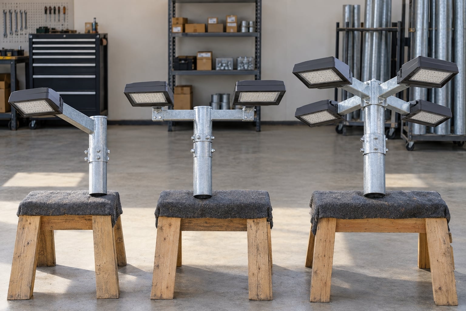
Choose Single, Twin or Four-Fixture Top Brackets
Single fixture
Useful at perimeters or narrow edges where light is directed mainly toward one side and backlight must be controlled.
Twin opposite fixtures
Often suits long parking rows or narrow islands where two luminaires serve opposite parking areas or aisle directions.
Four fixtures
Can serve broad interior islands when the photometric layout needs coverage in four directions and the pole is designed for the combined load.
Fixture count alone is not enough. The bracket drawing should show arm length, section, bolt pattern, spigot diameter, insertion, tilt and orientation. The complete luminaire and bracket exposed area contributes to structural demand, especially for compact poles with several fixtures.
Perimeter, Row and Interior-Island Pole Placement
Perimeter poles usually direct most light inward and may need tighter backlight control. Row poles can use twin fixtures along a long axis. Interior islands can support multi-directional brackets, but the island must provide adequate foundation space and protection from vehicles. The pole centerline, curb face and parking overhang should be dimensioned together.
Placing a pole at every island may simplify drafting yet create unnecessary structures. Conversely, stretching spacing to reduce pole count can lower uniformity or increase fixture output and glare. Compare layouts using both photometric results and civil total number of foundations, cable routes and maintenance positions.
Protect Vehicle and Pedestrian Clearance
Locate shafts, bases and access doors away from expected vehicle overhang, turning paths and door-swing areas. Where curbs or barriers provide protection, their geometry should be shown rather than assumed. Pole placement must also preserve accessible routes, sidewalk ramp clearances and sight lines at internal junctions.
Maintenance vehicles need a safe standing position without blocking critical access. Door orientation should let technicians work from a protected side. Local codes and site owners may specify setbacks, impact protection or breakaway behavior; the project designer determines which requirements apply.
Round and Polygonal Tapered Shaft Options
A parking lot lighting pole can use a round tapered, polygonal tapered or straight shaft. Selection may depend on appearance, manufacturing method, required stiffness, door detail and the top diameter available for bracket and electrical interfaces. Shape should remain consistent across the schedule unless different zones intentionally use different families.
Taper, base dimension, top dimension and section length work together. These dimensions should be derived from the design rather than selected independently. If transport requires segmented shafts, the slip-joint or flange connection and assembly procedure become part of the supplied configuration.
Steel Grade and Wall Schedule Follow the Load Basis
Steel grade and wall thickness affect strength, stiffness, fabrication and mass, but a single standard value is not appropriate for every pole. The design also depends on shaft diameter, taper, door opening, bracket geometry, base detail, height and governing load combinations. A stronger steel grade does not compensate for an uncoordinated top load or inadequate connection.
The quotation should identify the proposed material basis and the data still required for finalization. Where local standards specify material equivalents, documentation should use consistent grades and units. Final production dimensions belong on approved fabrication drawings.
Wind Basis and Effective Projected Area
Wind acts on the shaft, bracket, luminaires and accessories. The exposed area, drag behavior, mounting height and eccentricity of every top component contribute to shear, moment and sometimes torsion. A four-fixture head can impose a different demand from a visually similar twin fixture arrangement.
Provide the project location, governing standard, basic wind parameter, exposure or terrain information, topography, importance or risk category where used and luminaire dimensions. The wind-load and EPA RFQ guide explains how to assemble a reviewable structural input set without relying on a context-free marketing wind number.
Luminaire Data Required for Pole Design
Send the fixture manufacturer, model, quantity, mass, overall dimensions, mounting method, insertion, tilt and exposed-area information. Include control devices, photocells, cameras or signs mounted at the top because small accessories can add eccentric load or change wind area. A product brochure image is not enough for connection design.
Confirm whether luminaires arrive with the pole package or from another supplier. When separate, the interface drawing should be approved by both sides. The bracket should not be fabricated around an estimated spigot if the final fixture has a different bore or clamping length.
Base Plate and Anchor-Bolt Interface
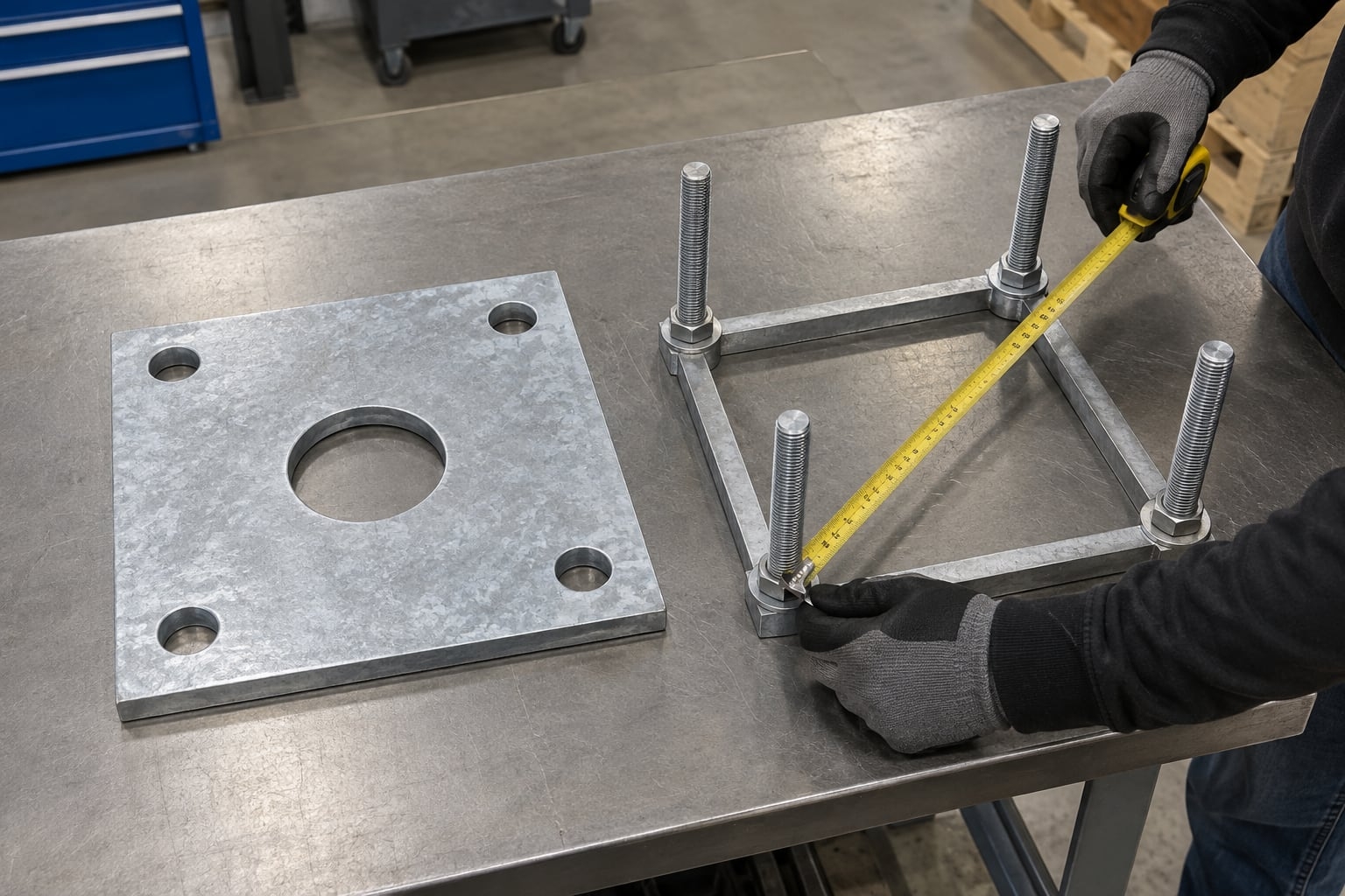
The base drawing should state plate size and thickness, shaft position, stiffeners, bolt-hole coordinates or circle, central cable opening and orientation. The matching anchor detail identifies bolt material, thread, projection, template geometry, nuts and washers. Enough clearance is needed for tools, cables and any base cover.
Foundation design remains site-specific. Soil, groundwater, frost, slope, drainage, utilities and pole reactions all matter. The foundation and anchor bolt guide covers this civil interface in detail.
Direct-Burial Base Option
Some parking areas use an embedded shaft rather than a base plate. A direct-burial galvanized pole can reduce exposed anchor hardware, but it changes the civil detail, drainage, cable entry and future replacement method. The embedded section and protective treatment must be coordinated with soil and site conditions.
Do not assume one embedment depth or backfill method. The project design should define the hole, surround, compaction or concrete, temporary support, finished grade and inspection requirements. Keep the product schedule clear so flanged and embedded poles are not mixed at delivery.
Coordinate the Foundation With Islands and Drainage
Parking islands are often small and may contain irrigation, trees, drains or shallow services. The foundation footprint, anchor cage and conduits must fit without compromising required cover or landscape features. Finished pedestal height should consider mulch, paving, snow clearing and future resurfacing.
The base should remain inspectable and should not sit in a pocket that holds water, salt or soil. Civil drawings should show curb geometry, top elevation and drainage direction. A visually neat island can still create a poor pole environment if runoff is directed toward the base.
Access Door and Internal Cable Path
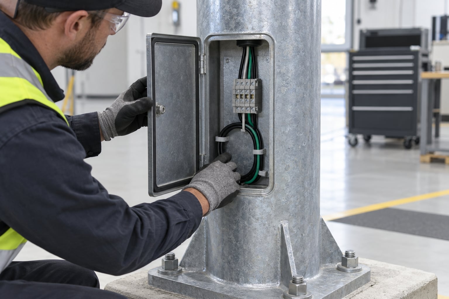
The access opening should provide space for the specified terminal equipment, fuses, surge devices, connectors and cable bend radius. Door size, position, frame and reinforcement are coordinated with the structural design. The opening should face a maintainable side and remain clear of parked vehicles and landscaping.
Internal edges and transitions should protect cable insulation. A retaining chain or secure door hardware can help prevent loss during maintenance. The delivered door and fastening method must match the shaft rather than rely on a loose universal cover.
Earthing, Bonding and Internal Equipment
Provide an internal earthing or bonding point where required by the electrical design. Connection materials, conductor routing and testing follow the governing electrical requirements and the site system. Structural anchors should not be assumed to provide the electrical function unless the approved design explicitly says so.
Clarify which internal components are included in the pole supply. A complete schedule can identify terminal blocks, protection, surge devices, driver location, control wiring and cable glands. This prevents each bidder from including a different boundary of supply.
Hot-Dip Galvanizing for Outdoor Steel Poles
Hot-dip galvanizing protects external and internal steel surfaces through a zinc coating formed after fabrication. The fabrication sequence should allow drainage and venting, and sealed cavities must be avoided. Chemistry, surface preparation, steel composition, geometry and withdrawal all influence the finished coating.
The project specification should state the governing coating requirement and inspection basis. Appearance can vary across welds, edges and steel batches without automatically indicating failure. Acceptance should use the specified criteria, not a catalogue photograph. Threads and mating surfaces need a compatible detail so nuts and brackets fit after coating.
Duplex Coating and Project Color
A color topcoat over galvanizing may be selected for corporate campuses, retail sites, residential developments or more aggressive exposures. This duplex approach requires compatible preparation, coating materials, film build, curing and handling. The buyer should state the color reference, gloss range and environmental category rather than request “black paint” without a system.
Coated poles need padded packing and controlled lifting to reduce scratches. Where salt, deicing chemicals or coastal exposure are significant, review the complete corrosion-control detail. A duplex-coated lighting pole page provides a deeper treatment of these choices without promising a universal service life.
Detail Drainage and Water-Shedding Surfaces
Top caps, bracket joints, cable entries, doors and base details should prevent uncontrolled water entry while allowing intended drainage or ventilation. A decorative base cover must not trap water, soil or deicing residue against anchors and the plate. Landscape irrigation should be aimed away from the access opening and electrical equipment.
Drawings should show whether bracket ends are capped, how cables pass through the top and how the base is supported. Site sealants should not block designed drainage paths. A clear detail is more reliable than expecting installers to improvise after the pole arrives.
Manufacturing Sequence for the Pole Assembly
A typical project proceeds from approved material and drawings through cutting, forming, longitudinal welding, base and door fabrication, bracket production, dimensional inspection, surface treatment, trial fit, final checks and packing. The exact route depends on shaft type, connection details and finish system.
Revision control is essential because several visually similar poles may share production. Stable item marks link the shaft, bracket, base, anchor template and packing list. Hold points should match the project's documentation requirements instead of being added after fabrication is complete.
Welding and Dimensional Inspection
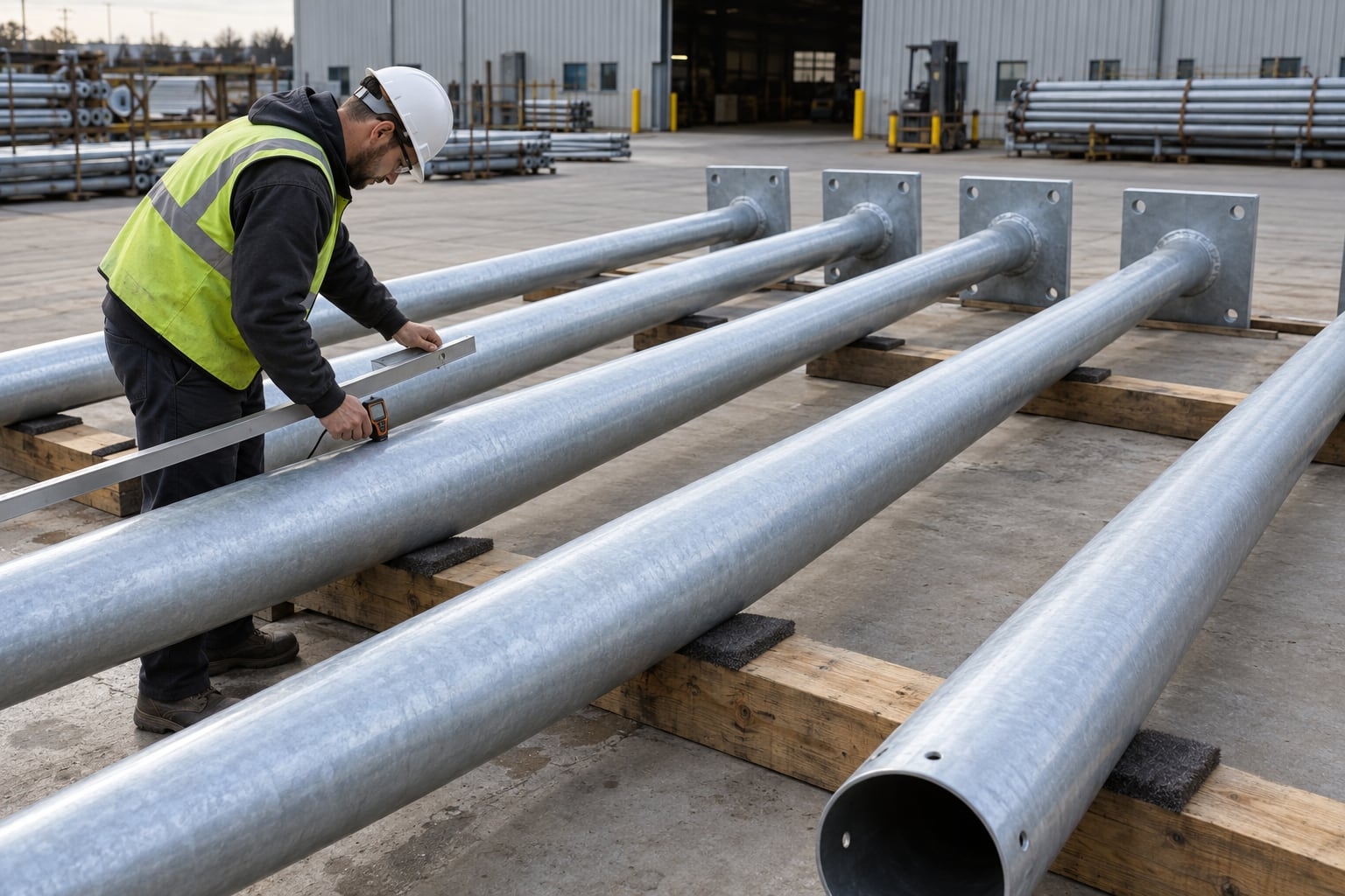
Inspection should confirm shaft straightness, length, taper, cross-section, door position, top diameter, base orientation, bolt-hole pattern, bracket dimensions and fit. Weld examination follows the approved procedure and acceptance criteria for the design. Door corners, base welds and bracket connections deserve particular attention because they alter the local load path.
Dimensions should be recorded against the released drawing. A pole can look straight yet have a top diameter that does not match the bracket or a base pattern that differs from the foundation. Early checks allow correction before galvanizing and packing.
Galvanizing and Finish Inspection
After surface treatment, inspect coating coverage, drainage areas, rough projections, runs, contact marks, repaired areas and threads using the specified method. The internal coating and drainage openings should be considered where accessible. Sharp zinc points that could damage cables or workers need appropriate treatment without reducing required protection.
For a duplex finish, add checks for color, curing, adhesion or film thickness as required by the approved system. Record repairs and protect the finished surfaces during storage. Quality documentation should identify the pole item or batch it covers.
Trial-Fit Top Brackets and Luminaires
Trial fitting verifies spigot diameter, insertion, bolt alignment, bracket orientation and cable path before the parts are separated for shipment. When the actual luminaire is available, confirm its clamp engagement and tilt range. If it is supplied by another party, use an approved interface drawing and, where practical, a representative sample or verified dimensions.
Mark each bracket and related shaft so site teams can assemble the correct pair. Protective caps should keep water and debris out during storage. Fasteners should be bagged and identified rather than placed loose inside a long shaft.
Pack Poles, Brackets and Hardware for Transport
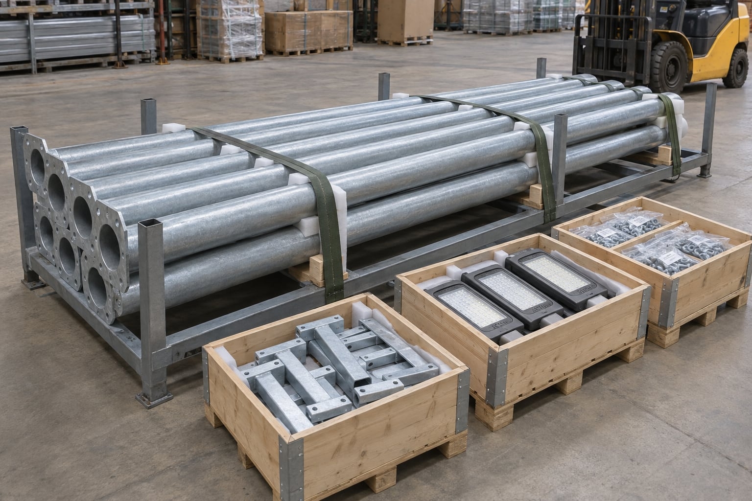
Long shafts should be supported and restrained so they cannot roll, rub or bend during inland and sea transport. Separate layers with suitable spacers and protect flanges, doors and coated surfaces. Luminaires, brackets and electrical parts need individual crates or reinforced packaging suited to their fragility.
Pack hardware by item group and include a traceable list. Container loading should consider unloading sequence and available site equipment. A tightly loaded bundle is useful only if the customer can remove the poles safely without damaging adjacent items.
Plan Installation Before Shipment Arrives
Coordinate delivery access, storage supports, crane position, lifting points, orientation marks and work-zone controls before the containers arrive. Foundations should be released and measured against the approved base drawing. The crew needs the correct nuts, washers, brackets and cable provisions for each item mark.
The installation plan should cover receiving, lifting, plumb, cable pulling and handover. Ground preassembly can reduce work at height, but the complete bracket and luminaire arrangement must be included in the lifting plan and protected from impact.
Provide Safe Maintenance Access
Locate poles so a lift truck or other approved access method can reach luminaires without crossing soft landscape, blocking an emergency route or extending above parked vehicles. Door orientation should give technicians a protected standing area. Trees should be considered at mature size, not only at planting.
Group controls and circuits logically so maintenance teams can isolate the correct area. Record fixture model, aiming, driver or control location and pole identifier. Replaceable brackets or standardized interfaces can help future work when they are included from the design stage.
Commercial, Industrial and Public Parking Applications
Retail and office parking
Coordinate pedestrian routes, storefront glare, landscape islands, evening schedules and a finish compatible with the site architecture.
Industrial employee lots
Plan shift-change operation, larger access aisles, security interfaces, durable finishes and maintenance without interrupting production access.
Public transport parking
Separate bus, car, taxi, cycle and pedestrian zones; coordinate controls with extended operating periods and emergency circulation.
Schools and campuses
Control glare near residences, protect accessible routes and align pole appearance with walkways, sports zones and building lighting.
Healthcare parking
Support clear entrances, drop-off routes and continuous pedestrian visibility while preserving ambulance and service access.
Residential developments
Use appropriate mounting scale, backlight control and finish while maintaining safe access and limiting intrusion toward windows.
Typical Configuration Choices
| Decision | Available direction | Project input that controls it |
|---|
| Placement | Perimeter, row, island or building approach | Site plan, bay geometry, setbacks and target surfaces |
| Top arrangement | Single, twin or multi-fixture bracket | Photometric layout, fixture size, mass and exposed area |
| Shaft | Round, polygonal, straight or tapered steel | Height, appearance, structural design and bracket interface |
| Base | Flanged with anchors or direct burial | Civil design, soil, drainage, replacement and owner preference |
| Finish | Galvanized or galvanized plus compatible color coat | Exposure, appearance, maintenance and project specification |
| Electrical | Door, terminals, protection, controls and earthing provisions | Single-line diagram, circuit design and maintenance plan |
This table organizes decisions; it does not prescribe dimensions. The final pole schedule should state the chosen configuration and reference the approved drawings that define each interface.
Parking Lot Light Pole RFQ Checklist
Site and environment
Location, governing standards, wind basis, terrain or exposure, corrosion conditions, temperatures and site restrictions.
Lighting layout
Plan, calculation criteria, mounting height, pole spacing, fixture schedule, optical files, tilt and orientation.
Pole configuration
Shaft shape, base type, bracket family, access door, finish, color and required accessories.
Civil interface
Foundation responsibility, soil information, base and anchor drawing, cable conduits and finished levels.
Electrical interface
Cables, terminals, protection, earthing, controls, glands and boundary of supply.
Delivery and documents
Quantity by item, packing limits, port, unloading method, drawings, calculations, inspection and handover records.
Compare Supplier Quotations on the Same Basis
Place each proposal against the same pole schedule and identify deviations. Compare shaft geometry, material basis, top loads, bracket details, base and anchor scope, finish system, internal equipment, packing, drawings and inspection records. A low total may exclude anchors, brackets, luminaires or design documentation that another bidder includes.
Ask suppliers to separate confirmed values from assumptions and to state what data is needed before production. A proposal that lists only height and wall thickness is not enough to verify compatibility with the photometric, civil and electrical design.
Common Parking Lot Pole Procurement Errors
- Choosing pole height before the photometric calculation and maintenance plan are defined.
- Adding fixtures without updating wind area, bracket design, shaft reactions and foundation inputs.
- Ordering a base plate before the civil team confirms the foundation and anchor interface.
- Using one bracket drawing for luminaires with different mounting bores, masses or optical directions.
- Placing poles where vehicle overhang, accessible routes, trees or underground services create conflicts.
- Specifying a color without defining the full preparation and compatible coating system.
- Leaving internal electrical equipment, earthing and door orientation outside the supply schedule.
- Accepting unsupported universal wind, service-life or foundation claims instead of project documentation.
A coordinated RFQ prevents most of these issues before they reach fabrication. Use drawings and stable item marks so the supplier, consultant and contractor are discussing the same assembly.
Night-Time Layout and Commissioning
After installation, confirm that every luminaire matches its position, orientation and control group. Electrical testing, earthing checks and control commissioning should follow the project requirements. A night review can reveal reversed optics, unexpected shielding, trees blocking light, inconsistent aiming or circuits that do not respond as scheduled.
Compare field conditions with the approved lighting layout and document necessary adjustments. Visual appearance alone does not replace measured or calculated acceptance criteria, but it is useful for identifying obvious installation mismatches before handover.
Lighting Controls and Circuit Grouping
Parking demand changes through the evening, but controls should preserve required visibility and avoid abrupt dark zones. The electrical designer can group perimeter rows, interior bays, entrances, pedestrian routes and after-hours areas according to the operating plan. Time schedules, photocells, local switching, dimming or network controls may be used when compatible with the luminaires and project requirements.
The pole schedule should identify control components that affect the shaft or bracket, including photocell sockets, antennas and cable quantities. Group identifiers belong on drawings, panels and handover records. If part of the site dims after closing, the lighting calculation should check the reduced operating scene rather than assume that every circuit always runs at full output.
Coordinate Cameras, Signs and Other Pole Attachments
Security cameras, wireless devices, signs, banners and speakers may appear small beside a tall pole, yet they can add wind area, mass, cable routes and maintenance access. Declare every proposed attachment before structural design. Its height, offset, projected area and connection method should be shown on the approved pole arrangement.
Do not drill or weld field brackets onto a completed galvanized shaft without engineering and coating review. A multi-purpose need may justify a dedicated engineered pole rather than an improvised modification. Keep the primary street light pole range distinct from traffic-signal or smart-pole structures that carry different equipment and access requirements.
Standardize Pole Families Without Hiding Real Differences
Owners often prefer a small number of standard pole families because repeatable brackets, doors and finishes simplify spares and maintenance. Standardization is useful when the photometric and structural inputs fit within a documented envelope. It should not erase genuine differences between perimeter single-head poles, interior four-head poles and taller special locations.
A project schedule can use a common appearance while retaining several engineered item codes. For example, a galvanized finish, door style and general shaft profile may remain consistent while top loads and base details vary. Height-specific roadway products such as a 10 m single-arm pole should not be substituted automatically for a parking-area configuration with a different bracket and load direction.
Replacement and Retrofit Survey Requirements
When replacing existing parking lot poles, survey the foundation, anchor coordinates, bolt diameter and projection, pedestal condition, cable entry, circuit, pole height, top arrangement and luminaire orientation. Matching the visible bolt pattern does not prove that the old foundation can carry the new shaft and fixture reactions. Available original drawings and the condition of concealed components should be reviewed.
A retrofit may keep the existing mounting height but change the luminaire mass, exposed area or bracket geometry. Provide the new fixture data and ask the responsible engineer to compare the complete load basis. If an adaptor is proposed, its connection, clearances, corrosion protection and effect on mounting elevation need documented approval rather than site fabrication by assumption.
Frequently Asked Questions
What height should a parking lot light pole be?
Select height through the photometric layout, site scale, wind design and maintenance method rather than a universal value.
Can one pole carry four LED fixtures?
Yes, when the bracket, shaft, base and foundation are designed for the actual combined loads and wind area.
Is a twin T bracket suitable for every parking row?
No. Fixture orientation and spacing should follow the actual target surfaces and optical calculation.
Can the pole be powder coated over galvanizing?
A compatible duplex coating can add color and protection when preparation and curing follow the approved system.
Is the anchor-bolt pattern standard?
No. It should match the approved pole base and project-specific structural design.
What fixture data does the pole supplier need?
Provide quantity, mass, dimensions, mounting bore, insertion, tilt, exposed area and accessory details.
Can parking lot poles use direct burial?
Yes, when the embedded section, soil interface, drainage, cable entry and replacement plan are designed for the site.
Which way should the access door face?
Face it toward a safe, maintainable position coordinated with traffic, curbs and the electrical route.
Are foundations included with the pole?
Scope varies. Define who supplies anchors, reactions, reference drawings and final civil design in the RFQ.
Can wall thickness be selected by height alone?
No. Shaft geometry, material, openings, bracket, luminaires, wind basis and load combinations all matter.
How should long poles be packed?
Support and restrain shafts, separate finished surfaces and crate brackets, luminaires and hardware by item.
What records should be handed over?
Use the contract list, commonly including drawings, inspection, coating, installation, electrical test and as-built records.
Send a Reviewable Parking Lot Pole Schedule
Provide the site plan, mounting heights, luminaire photometry and dimensions, bracket directions, wind basis, finish, base type, foundation responsibility, electrical scope, quantities and destination. Jieyao can return a coordinated parking lot light pole proposal with project-specific interfaces for buyer and consultant review.
Request a Parking Lot Light Pole Configuration