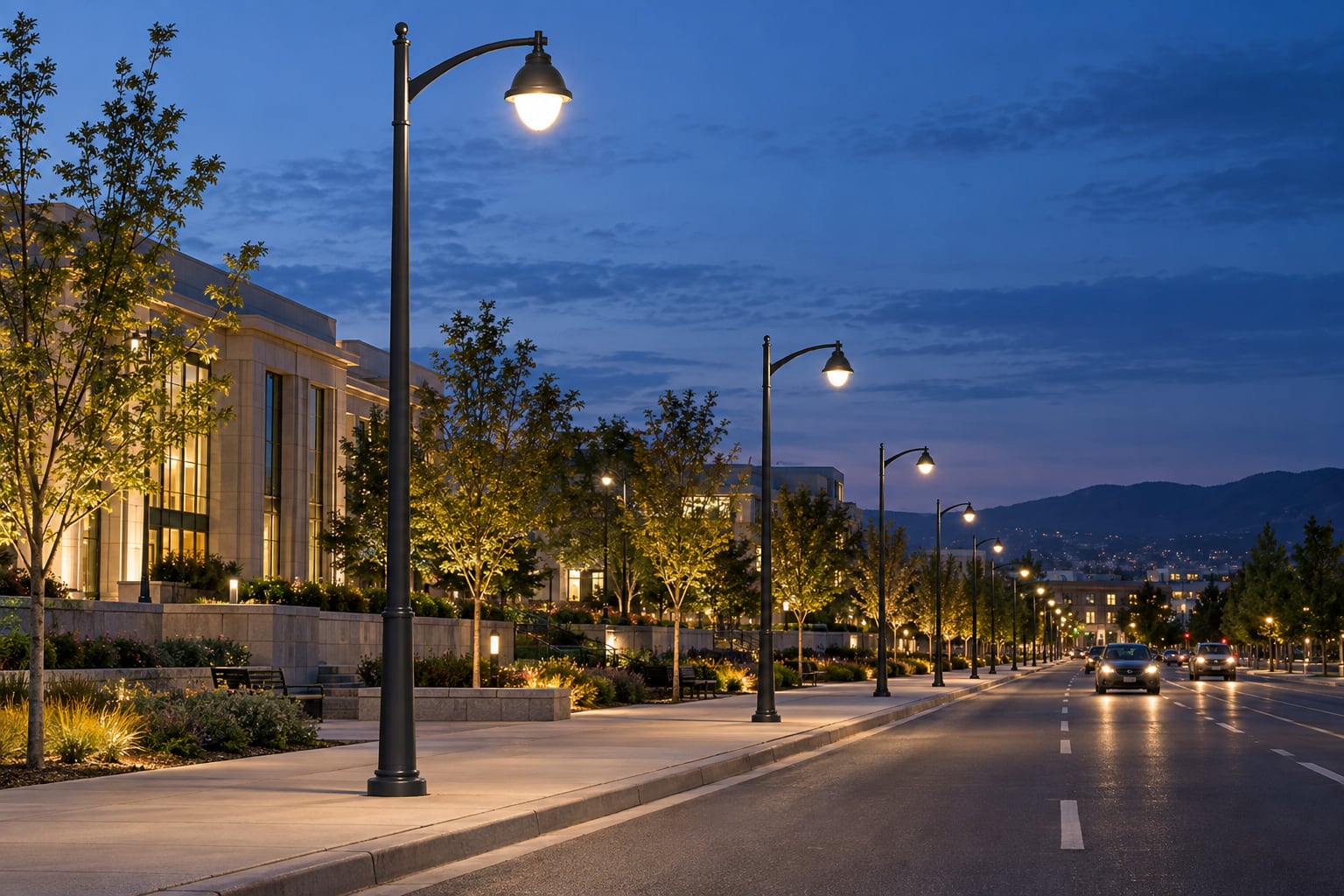
A Decorative Street Light Pole Is Still an Engineered Structure
A decorative street light pole combines visible streetscape character with the same structural, electrical and installation responsibilities as a conventional roadway pole. Its shaft supports the luminaire, arm, finial, optional signs and other declared attachments while remaining stable under the project wind basis. Its geometry must also provide cable access, a practical base interface and repeatable orientation.
Appearance should be developed with those functions, not applied after they are fixed. Jieyao prepares project-configured galvanized steel poles with coordinated decorative sleeves, collars, arms and colored finishes. Final dimensions, material schedule and connection details follow the approved top load, governing standard, site exposure and architectural direction.
For procurement, the useful product is the complete documented assembly: shaft, top connection, decorative components, base interface, access provision and finish. Keeping these items under one pole mark makes technical review, quotation comparison, installation and later replacement substantially clearer.
Match the Pole to the Application Zone
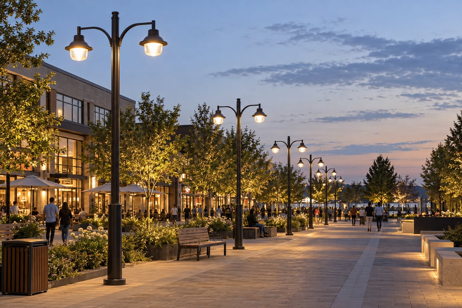
Boulevards, pedestrian streets, parks, plazas, campuses, waterfront promenades and commercial districts do not use decorative lighting in the same way. A traffic route may need a longer side arm and controlled road optic. A square may use post-top luminaires with shorter spacing. A promenade must respect pedestrians, trees, seating and views.
Divide the project into zones before selecting the pole family. Record road width, setbacks, path edges, planting, building entrances, vehicle clearance, operating hours and maintenance approach. One visual language can connect the site, while each zone receives the correct mounting and photometric arrangement.
Create a Repeatable Streetscape Family
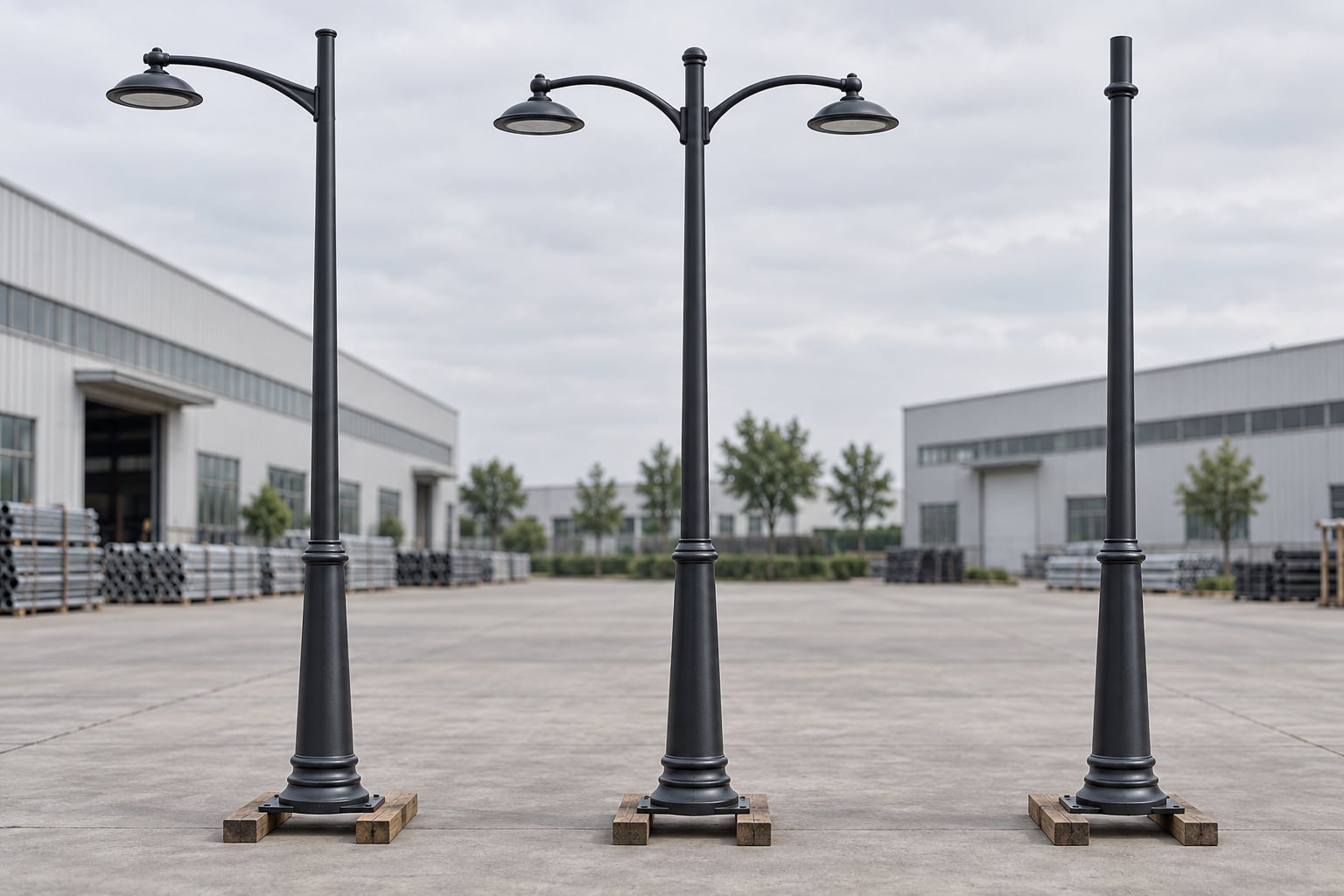
A strong decorative system uses a small set of related components rather than a different pole at every location. Establish the principal shaft profile, base treatment, collar vocabulary, arm curvature, finial and finish. Then define controlled variants for single-arm roadsides, twin-arm medians, post-top paths or coordinated sign attachments.
Repeatability improves drawing control, fabrication consistency, spares and future extensions. The family schedule should identify which parts are structural, which are removable decorative covers and which interfaces are shared. This helps buyers compare equivalent offers and reduces the risk of a replacement pole looking noticeably different.
Translate the Architectural Reference Into Procurement Data
An architectural elevation may show the desired silhouette without defining steel thickness, connections, access or top loading. Keep that reference as a visual-control document, then add dimensioned pole and component drawings for manufacture. Identify the features that must remain fixed—such as shaft proportion, arm curve, collar positions and luminaire relationship—and the details suppliers may engineer within the project requirements.
Provide scale views from the main pedestrian and vehicle approaches, not only a front elevation. If an existing streetscape is the reference, record measurable dimensions, finish samples and interface details rather than relying on distant photographs. The resulting package lets the manufacturer preserve the intended character while proposing a repeatable, inspectable steel assembly.
| Design input | What it controls | Procurement output |
|---|
| Architectural elevation | Overall silhouette, proportions and visible component relationships | Controlled dimensioned pole profile |
| Photometric layout | Mounting height, outreach, fixture orientation and pole positions | Zone-specific pole and arm schedule |
| Luminaire data | Mounting interface, weight, EPA, cabling and visual scale | Approved spigot or adapter detail |
| Structural basis | Wind, exposure, topography and complete attachment loading | Shaft, base and connection design inputs |
| Finish reference | Color, gloss, texture and repair expectations | Approved coating system and sample |
Choose Straight, Tapered or Stepped Shaft Geometry
Round tapered steel shafts create a clean continuous line and suit many restrained decorative concepts. Polygonal tapered shafts can provide another visual expression while using formed steel construction. Stepped assemblies may separate a stronger lower shaft from a smaller upper section, but their joints and proportions must be intentionally detailed.
Choose geometry with the designer and structural engineer. Check the visible silhouette from pedestrian eye level as well as the section properties needed for the complete top assembly. Avoid adding abrupt decorative changes where they complicate drainage, coating, cable pulling or inspection.
Configure Single-Arm, Twin-Arm and Post-Top Variants
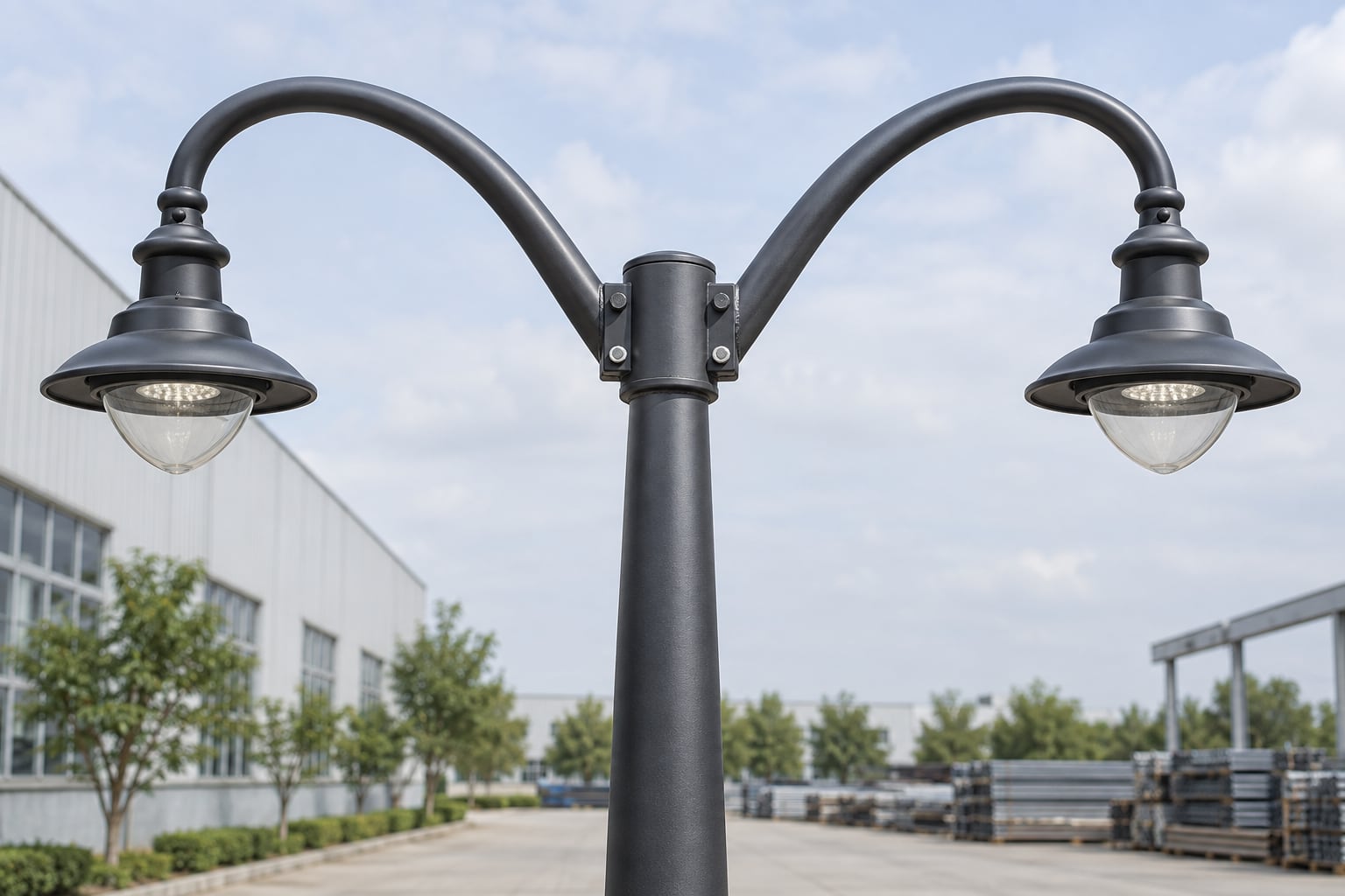
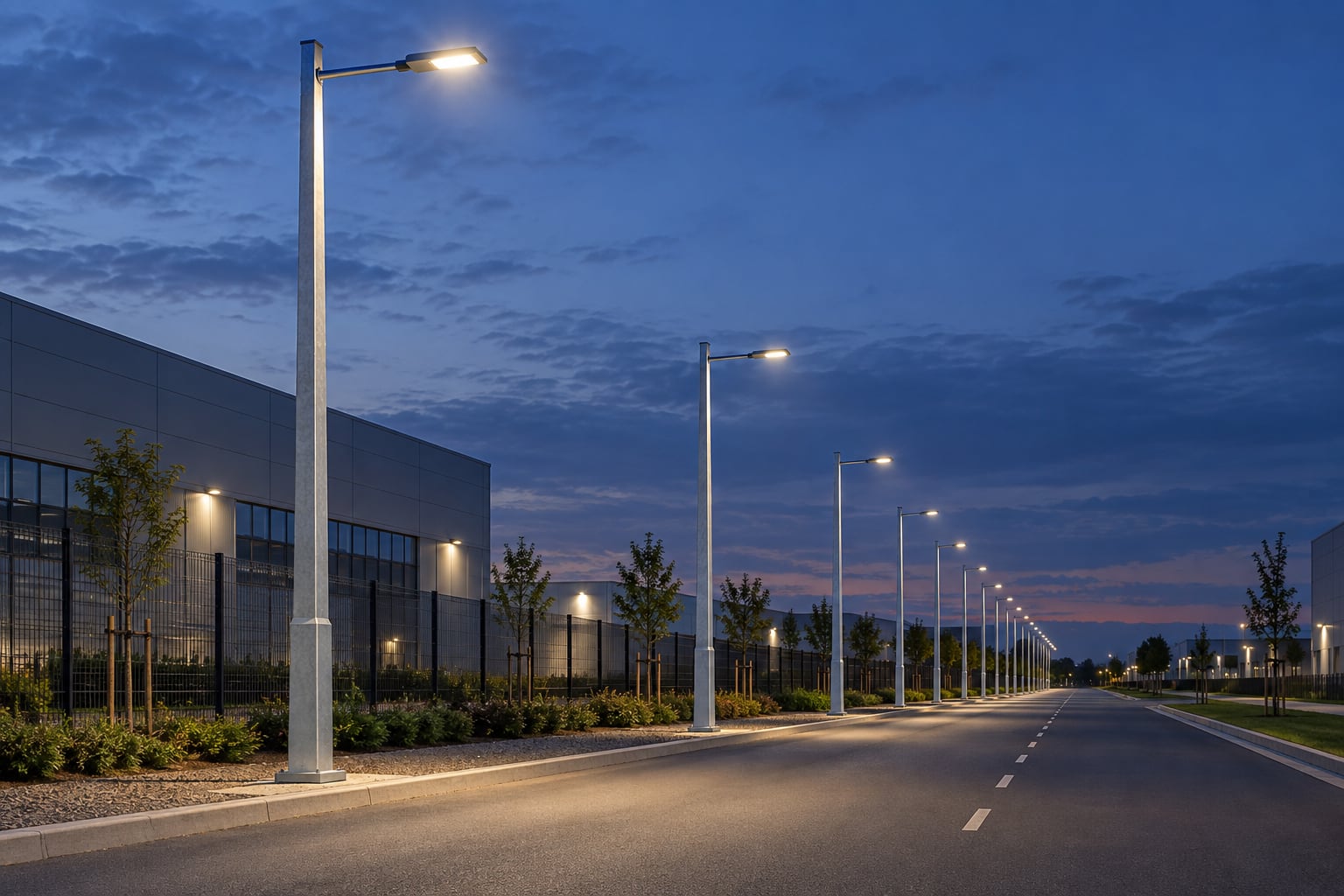
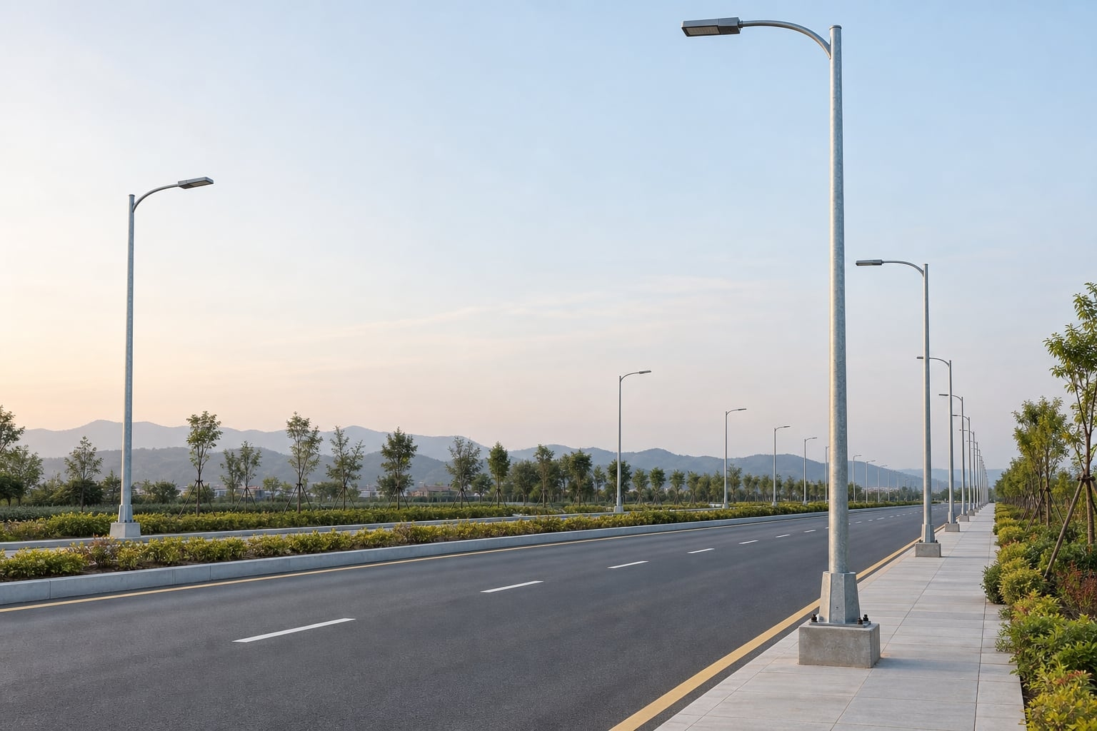
A single side arm can place a roadway luminaire over the carriageway while keeping the shaft behind the curb. Symmetric twin arms can serve a median, central promenade or two-sided path where the photometric model supports them. A post-top connection creates a compact profile for pedestrian-scale areas and some plazas.
The arrangement is selected from the lighting calculation and site geometry, not from a catalogue silhouette alone. Arm reach, rise, tilt, luminaire orientation and fixture mass belong in the schedule. A decorative steel lamp post can look balanced while still providing a precise, documented mounting interface.
Engineer Decorative Arms as Real Connections
Curved arms must transfer load into the shaft through a defined sleeve, flange, welded bracket or other engineered connection. Smooth visual lines should not hide thin transition zones, inaccessible fasteners or water traps. The approved drawing identifies connection plates, bolts, welds, cable route and assembly sequence.
For export and replacement work, detachable arms can simplify packing and field service. Their indexing should prevent reversed assembly, and the cable path should be protected at every edge. Decorative scrolls or braces that are not structural should be clearly distinguished from load-carrying members.
Coordinate the Luminaire Interface and Visual Scale
The luminaire determines more than the appearance at the top of the pole. Provide its mounting method, spigot dimensions, weight, EPA, center of gravity, cable entry and adjustment range. Confirm whether it is side-entry, post-top, pendant or uses a dedicated adapter. The adapter should not rely on improvised site drilling.
Review scale in elevation. An oversized lantern can dominate a modest shaft, while a small fixture may look lost on a broad boulevard. Use dimensioned drawings or physical samples to judge proportion, but use photometric data and structural inputs to approve performance and loading.
Select Mounting Height Through the Lighting Layout
Mounting height affects spacing, uniformity, glare, pole count, visual scale, structural demand and maintenance equipment. Lower poles can support an intimate pedestrian environment but may require closer spacing. Taller poles may cover a wider road while appearing less detailed from the ground. The correct balance is project-specific.
Model the proposed luminaire at the actual mounting height, setback and arm position. Include road lanes, sidewalks, crossings, seating and vertical surfaces when relevant. Do not transfer a spacing rule from another street without checking its optics, maintenance factor, surface reflectance and required criteria.
Control Glare and Light Spill in Public Spaces
Decorative luminaires are often visible from many directions, so optical control matters. A bright glowing form does not prove that useful light reaches the road or path. Review intensity distribution, shielding, tilt and vertical brightness from driver, pedestrian, resident and camera viewpoints.
At homes, hotels, offices or habitat-sensitive boundaries, define spill and operating requirements with the responsible designer. Warm appearance, dimming and shielding can be considered without making unsupported promises. The approved photometric file should match the exact optical option installed.
Coordinate Trees, Furniture and Seasonal Use
Young trees can become major obstructions as their canopies mature. Place poles and select mounting heights with the landscape plan, allowing for realistic growth and pruning access. Avoid positions where branches will touch luminaires, hide the road optic or force repeated cutting that damages the intended planting form. Check irrigation spray and soil edges around the pole base as well.
Benches, signs, bins, market stalls and festival equipment also change how a public space works. Keep the access door and maintenance route clear in the normal and seasonal layouts. If temporary decorations or power outlets are planned, define their electrical and structural interfaces instead of attaching them informally after installation.
Define Wind and EPA for Every Visible Attachment
The structural design uses the governing wind basis, exposure or terrain, topography, pole geometry and the complete projected area of the top assembly. Decorative lanterns, curved arms, finials, banners, signs, planters, cameras and seasonal elements can add area and eccentricity. Declare them before the shaft and base are approved.
A future banner is not a harmless accessory. If the owner may install one, its permitted size, position and support arrangement should be included in the project design. Undeclared attachments can invalidate the assumptions used for the pole, anchors and foundation.
Configure Steel Material and Structural Details
Material grade, thickness schedule, taper, seam weld, access opening, base plate and reinforcement follow the project calculations and fabrication method. Decorative proportions do not justify a universal wall thickness. The same visual pole can require a different structural schedule when height, wind or fixture configuration changes.
Request a marked manufacturing drawing that connects pole geometry to the material schedule. Openings and welded attachments must appear before release. If the contract requires structural documentation, specify the governing standard, design inputs, submission format and reviewing party in the RFQ.
Use Galvanizing Beneath the Colored Finish
A galvanized steel substrate provides a practical corrosion-protection base for many decorative poles. Vent and drain provisions must suit the fabricated hollow sections and remain compatible with the visible design. Welds, edges and threaded interfaces need appropriate preparation before the final color system is applied.
Describe the required galvanizing and post-treatment process in coordinated documents. Do not specify decorative powder coating as if it replaces substrate protection in every environment. The final system depends on exposure, color expectations, manufacturing sequence and repair plan.
Coordinate Powder Coating or Liquid Color Systems
Powder and liquid-applied systems have different preparation, curing, thickness, repair and color-control requirements. Define the coating family, approved substrate preparation, color reference, gloss range and touch-up method. Confirm that sleeves, threads, earthing points and slip-fit areas are treated appropriately.
A very thick decorative texture can obscure fastener seating or parting lines, while poor masking can block assembly. The supplier and coating specialist should review the full component set, including arms, finials, doors, collars and base covers, so mating parts remain functional.
Approve Color, Gloss and Texture With Samples
Color references are useful, but perceived appearance changes with gloss, texture, sunlight, nearby materials and batch conditions. Request a representative metal sample using the intended coating process. Review it beside paving, furniture and luminaire finishes where possible.
Set the approval hierarchy: written color code, physical sample, gloss tolerance and acceptable batch variation. Photographs on a screen are not a reliable final color standard. Retain an approved sample for receiving inspection and future replacement orders.
Keep Decorative Collars and Base Covers Serviceable
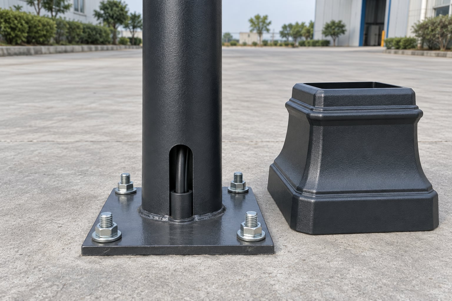
Collars, sleeves and base covers can create a deliberate transition between shaft and paving. Treat them as removable, inspectable components unless the project drawing states otherwise. They should not trap water, conceal loose anchors, block drainage or prevent technicians from reaching the access door.
Define attachment method, material, seams, finish and removal clearance. A base cover should fit the approved plate and anchor arrangement without forcing site cutting. If split covers are used, place joints consistently and keep fasteners accessible but visually controlled.
Coordinate Base Plates and Anchor Assemblies
The flanged base interface includes the shaft, base plate, stiffeners where required, anchors, nuts, washers, leveling or bearing method, grout where specified and foundation reactions. It is designed from the actual structural inputs. A decorative cover does not change the need for accessible, correctly tightened anchors.
Issue anchor setting dimensions before concrete work. The street light pole foundation and anchor bolt guide explains the information exchange between pole supplier, foundation designer and installer. Final foundation design remains with the responsible project engineer.
Consider Direct-Burial Interfaces Separately
Some projects use an embedded shaft rather than a base plate and anchors. That decision changes the lower pole geometry, cable entry, corrosion detailing, installation sequence and foundation concept. Do not convert a flanged decorative design by merely extending the shaft in a purchasing note.
Define the embedment interface with the project civil and structural designers. A dedicated direct-burial galvanized street light pole package can clarify the anchorless configuration. Decorative sleeves near grade must remain compatible with drainage, inspection and the specified underground protection.
Provide a Practical Access Door and Compartment
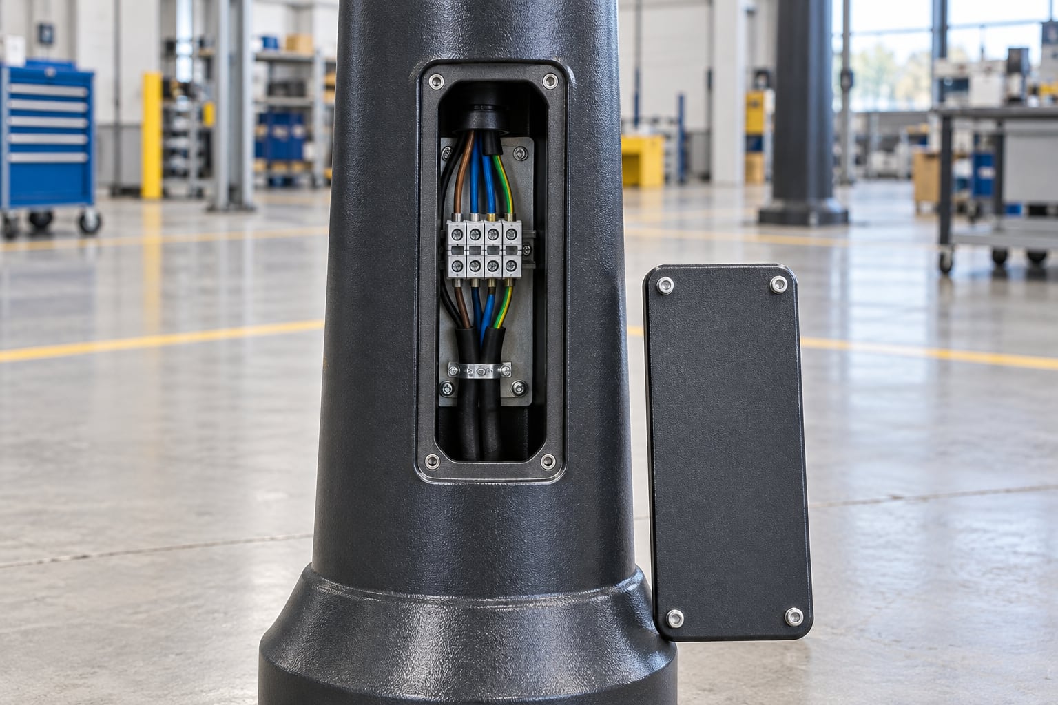
The access opening must allow the intended terminal equipment, cable manipulation and inspection without weakening the shaft beyond the approved design. Position it on a safe service side and identify its orientation relative to the arm. Reinforcement, door fit, fasteners and water management belong on the manufacturing drawing.
Decorative collars should not overlap the door or reduce working clearance. Use a retained, close-fitting cover suited to the project environment. The compartment layout is coordinated with the electrical designer and applicable safety rules; it should not become an improvised storage space for excess cable or controls.
Define Cable Entry, Earthing and Control Interfaces
Show conduit entry relative to the base plate or embedded section, then maintain a protected cable route to the access compartment and luminaire. Provide earthing provisions and terminal-space requirements according to the project electrical design. Sharp edges, blocked sleeves and undersized bends should be resolved before fabrication.
Photocells, dimming nodes or other controls may be located at the luminaire, inside the pole or in a remote cabinet. Identify responsibility, mounting, enclosure and communications needs. Added control hardware must remain accessible and must be included in the structural or electrical review when its location affects either.
Protect Streetscape Clearance and Accessibility
Pole placement must preserve the required pedestrian clear route, curb ramp, crossing visibility, cycle path, door swing and maintenance zone. Decorative bases can be wider than the shaft, so civil drawings should use the actual cover envelope rather than only the centerline. Check canopies, balconies and tree growth above.
At a road edge, coordinate setback with vehicle clearance, sight distance and local authority requirements. At plazas, keep poles from narrowing circulation or becoming unexpected obstacles. The responsible project designer sets final clearances and accessibility provisions for the location.
Manage Vehicle Impact and Maintenance Access
Delivery areas, parking edges and curbside loading can expose decorative poles to vehicles. Place the pole outside normal swept paths and identify any protective curb or barrier in the civil design. Protection should not block the access door, create a trip hazard or conflict with the foundation.
Plan how technicians will reach the luminaire and compartment. Confirm lift access, stable setup area, lane control, overhead hazards and safe door orientation. A beautiful pole becomes an operational burden if every routine service requires furniture removal or closure of a primary entrance.
Adapt the Finish to Coastal or Aggressive Exposure
Salt spray, de-icing salts, irrigation, industrial emissions and persistent moisture may require additional detailing or a project-specific duplex system. Describe the actual exposure, desired appearance and maintenance capability. Avoid relying on a generic “outdoor” coating statement.
Drainage, crevices, contact between dissimilar metals, fasteners and site repair are part of the protection strategy. For seafront roads and waterfront promenades, compare the dedicated coastal duplex-coated lighting pole approach with the decorative requirements rather than assuming color alone provides sufficient protection.
Develop Fabrication Drawings Before Production
The approval set should show overall height, shaft profile, seams, arm reach and rise, luminaire interface, decorative components, base or embedment detail, access opening, cable route, finish boundaries and orientation. Dimensions should use one consistent reference so the civil and lighting plans can coordinate the assembly.
Include a component list and pole marks for every approved variant. Where architectural elevations show visual intent, the manufacturing drawing translates that intent into buildable connections. Close comments before material release, and control later revisions through an agreed process.
Use Samples and Mock-Ups for the Right Decisions
A small coated metal coupon is useful for color and texture, but it cannot confirm whole-pole proportion. A component sample can check collar detail, fastener visibility or door fit. A full-scale mock-up may be justified where a large streetscape program has strict architectural interfaces, several observers and expensive repetition. Define the decision each sample must support before requesting it.
Record approval comments with photographs and dimensions, then return the accepted result to the controlled drawing set. Do not let a visual mock-up bypass structural or electrical review. If the sample changes the arm, fixture, attachment or base arrangement, update the corresponding engineering information before production.
Control Tolerances and Component Fit
Decorative parts make misalignment easy to see. Define tolerances relevant to shaft straightness, arm symmetry, top orientation, collar position, door fit and base-cover clearance. Check how accumulated tolerances affect a twin-arm silhouette or a repeated row of poles.
Trial-fit representative arms, luminaires, finials, doors and covers before shipment when the quality plan requires it. Avoid using coating build-up as a substitute for mechanical fit. Parts intended to be interchangeable should share controlled interfaces and permanent identification.
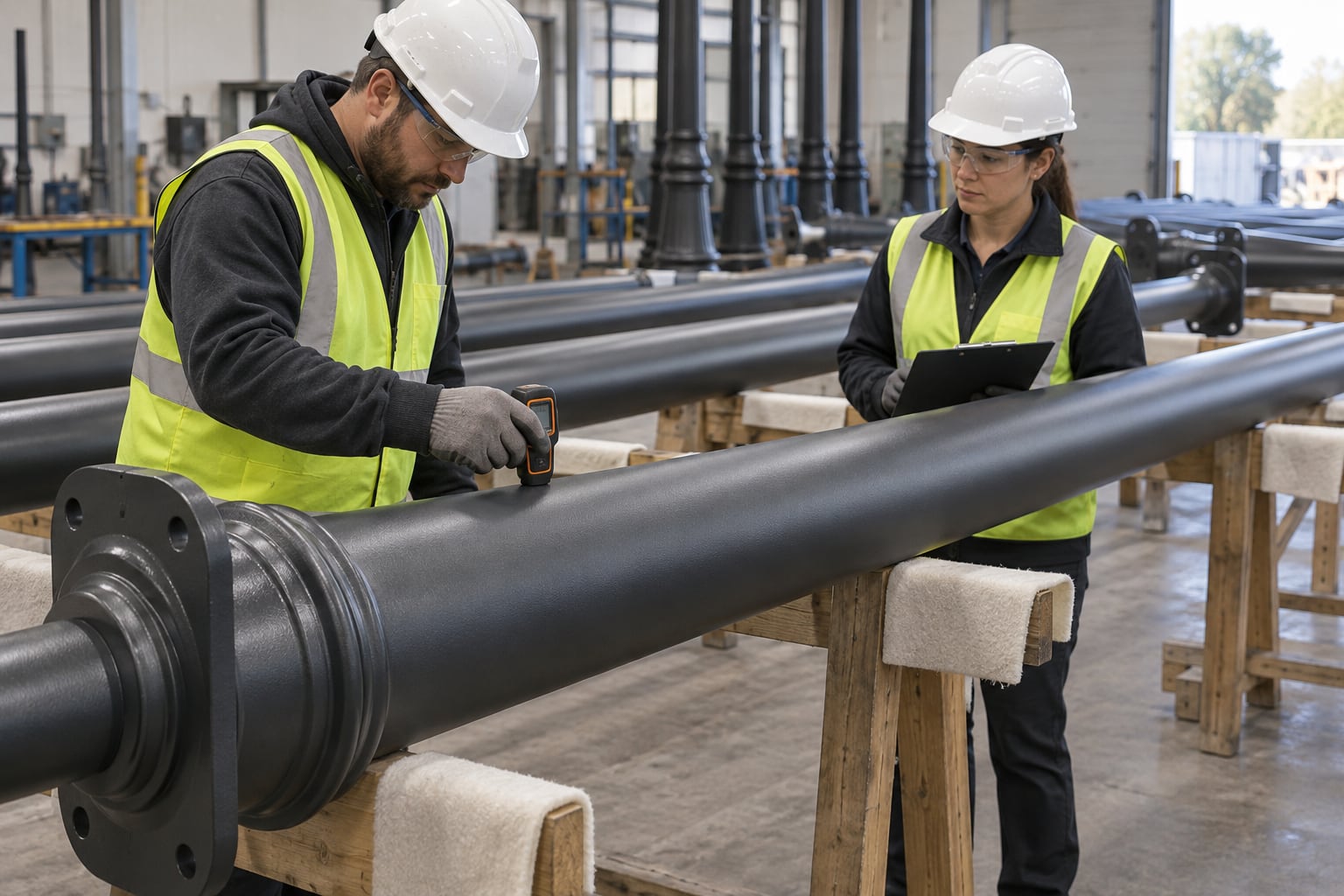
Inspect Fabrication and Protect the Finish
Inspection scope can include material identification, dimensions, welds, straightness, openings, fit-up, galvanizing and final coating, as required by the contract. Decorative surfaces also need a visual review under consistent light. Define records and acceptance responsibilities before production begins.
Handle coated parts with clean slings and padded supports. Small transport scratches should follow an approved repair procedure; severe impact or deformation requires engineering review. Photographs may support records, but they do not replace specified measurements or inspection documents.
Pack Poles, Arms and Covers as Separate Controlled Sets
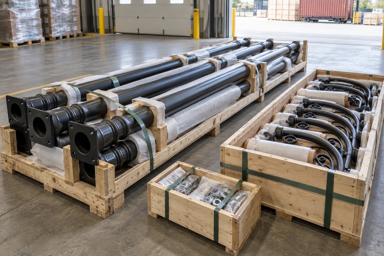
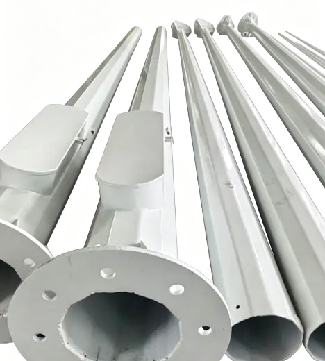
Long shafts need stable supports, spacing and restraints that prevent contact damage and bending. Protect finished surfaces from straps and timber edges. Detachable curved arms, luminaires, finials, doors, base covers and fasteners should be packed so their geometry and coating survive container handling.
Use package marks that connect each crate to the pole schedule without placing unnecessary stickers on visible finished surfaces. Include a packing list by component and variant. Provide lifting and storage instructions when required, and keep small hardware in sealed, identified packages.
Plan Installation Orientation Before Erection
On single-arm poles, the arm direction follows the approved photometric layout. Twin arms may require a precise road-axis orientation. Doors should face the safe service direction, and decorative seams or cover joints may have an agreed visual alignment. Mark these references on the drawings and components.
Before lifting, check anchor setting, foundation level, conduits, pole mark, finish condition and complete hardware. Follow the approved lifting plan and manufacturer instructions. The street light pole installation guide provides a broader receiving, erection and handover sequence.
Commission the Lighting and Review the Streetscape
After erection, verify verticality, arm symmetry, luminaire angle, door closure, fasteners, earthing, circuits and controls. Complete night commissioning with representative operating scenes. Record any aiming or dimming adjustments so future replacements reproduce the approved condition.
Also inspect the repeated visual line in daylight. Check collar heights, cover orientation, finish consistency and spacing relative to trees and furniture. A decorative product is accepted as a system: structural and electrical completion, photometric performance and visual coordination all need their own evidence.
Plan for Replacement and Streetscape Expansion
Retain the final drawings, color sample, coating system, luminaire interface, pole marks and component schedule. These records help the owner replace a damaged pole or extend the street without reverse engineering the original details. Identify which parts are standard and which were project-specific.
When a new luminaire, banner or camera is proposed, review its weight, EPA, connection and electrical requirements. Matching the color and general outline does not prove compatibility with an existing shaft or foundation. Treat substantive changes as an engineering check.
Define the Manufacturer and Supplier Scope
State whether the package includes the shaft, arm, spigot or adapter, finial, collars, base cover, base plate, anchors, access door, internal terminal arrangement, coating, drawings, calculations, inspection records, packing and delivery. Identify luminaires, foundations, installation and controls supplied by others.
A clear boundary prevents omissions and duplicate pricing. Jieyao can coordinate decorative galvanized steel pole fabrication and interfaces from approved project inputs. The project lighting, architectural, structural, civil and electrical designers remain responsible for the complete installed scheme within their scopes.
Prepare a Decorative Lighting Pole RFQ
Start with pole marks, quantities, application zones and the architectural elevation. Add mounting height, shaft geometry, arm arrangement, luminaire interface, complete top-load data, wind basis, base type, access opening, electrical provisions, finish system, color and required documents.
Attach the photometric layout, luminaire schedule, civil interface and reference details. State which decorative elements are mandatory and where suppliers may propose buildable alternatives. Include sample, mock-up or trial-assembly requirements only when the project needs them, and define who approves each submission.
Procurement checkpoint: confirm that the same pole mark connects the architectural elevation, photometric plan, structural inputs, foundation interface, electrical schedule and finish sample. A visually similar offer is not technically equivalent if its arm geometry, fixture load, base arrangement or coating sequence differs.
Compare Bids on Technical and Visual Equivalence
Compare complete assemblies rather than a single mass or price line. Review shaft material and geometry, arm connection, luminaire interface, base and anchor scope, access door, decorative components, galvanizing, color coating, documents, packing and exclusions. Confirm that bidders used identical wind and top-load inputs.
Record deviations beside the relevant pole mark. A heavier decorative casting does not automatically improve the steel pole, and a simplified collar may affect the approved streetscape. Close technical, visual and commercial exceptions before award so the accepted configuration can move directly into drawing development.
Avoid Common Decorative Pole Failures
Common failures include selecting a catalogue shape before photometric design, hiding anchors behind an inaccessible cover, allowing coating to block fitted parts, leaving arm direction ambiguous, using decorative scrolls as assumed structural braces and approving fixture changes without a wind review. Inconsistent batches can also make a repeated boulevard look disordered.
Prevent these problems with a controlled family schedule, complete top-load data, coordinated drawings, representative samples, trial fit-up and documented installation orientation. When any component changes, review the affected structural, optical, electrical, finish and civil interfaces rather than treating it as a cosmetic substitution.
Use Decorative Poles With the Right Related Products
For conventional roadway work where visual ornament is not the primary intent, begin with the street light pole range. A project-configured 8m galvanized pole may suit an urban road layout, while a dedicated parking lot light pole addresses multi-directional area-lighting brackets.
Decorative poles can coordinate with landscape fixtures, but the pole and luminaire remain separate specified interfaces. Link the correct product page from each application section so searchers and buyers can distinguish a streetscape pole, a road-height pole, an area-light pole and a garden luminaire.
Decorative Street Light Pole FAQs
Can the pole height be customized?
Yes. Height is configured from the lighting layout, visual scale, complete top load, wind basis and project requirements.
Can one design use single and twin arms?
Yes. Related variants can share the same shaft and finish while using approved arm interfaces for different zones.
Are decorative parts load-bearing?
Only when the approved structural drawing identifies them as load-bearing. Covers and collars are normally treated as separate components.
What luminaire data does Jieyao need?
Provide mounting details, dimensions, weight, EPA, center of gravity, cable entry and the intended orientation.
Can galvanized poles receive a color finish?
Yes. The coating system, preparation, color, gloss, masking and repair method must be coordinated for the project.
How is the decorative color approved?
Use a defined color reference plus a representative coated metal sample and agreed gloss or texture criteria.
Does a base cover replace anchor inspection?
No. The removable cover should preserve access to the approved base plate, anchors, cable entry and drainage.
Can banners or signs be added later?
Only after their area, weight, position and connections are checked against the pole and foundation design.
Are direct-burial versions available?
A direct-burial configuration can be reviewed, but its lower shaft, cable entry and foundation interface need separate design.
How are finished poles protected for shipping?
Shafts, arms and covers use suitable supports, padding, restraints and identified packages based on the delivery plan.
What should the buyer include in an RFQ?
Include pole marks, quantities, height, arm and luminaire data, wind inputs, base, finish, drawings and delivery scope.
Can replacement poles match an existing street?
Matching is more reliable when the original drawings, approved sample, interfaces and component schedule are available.
Request a Project-Specific Decorative Pole Review
Send the site plan, architectural pole elevation, photometric layout, luminaire data, wind inputs, base interface, finish requirement, quantities and document scope. Jieyao can review a buildable decorative galvanized steel street light pole family for the defined procurement package.
Submit Your Decorative Pole Requirements