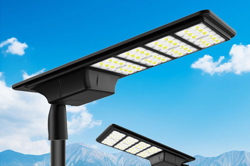


A street light pole shop drawing is ready for fabrication only when the location schedule, approved geometry, attached equipment, structural basis, civil/electrical interfaces, finish and revision status agree. Approving a nominal height or title block alone leaves critical mismatches undiscovered. Use one controlled comment register so the road designer, lighting consultant, civil engineer, supplier and installer know what has been accepted and what remains open.
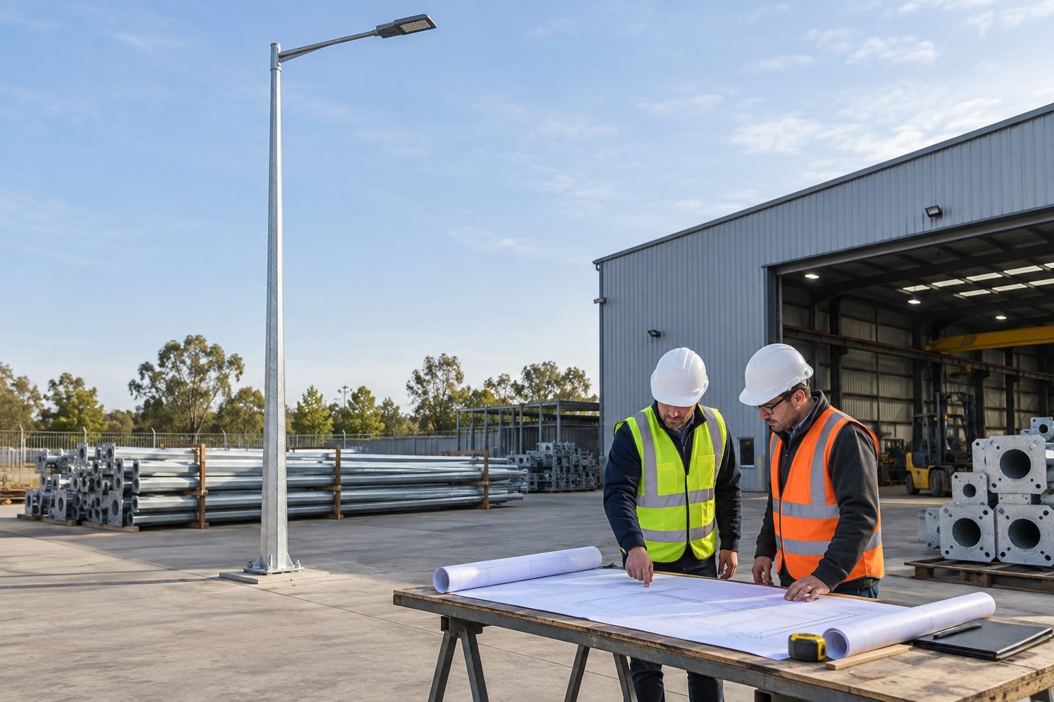
Coordinate the road layout, pole type and manufacturing interfaces before fabrication release.
Begin with the latest road plan, cross-section, pole schedule, luminaire data, equipment list, wind/exposure requirement and contract specification. Each pole type needs a mark and quantity, not just a marketing description such as “10 m galvanized pole.” Record whether height means shaft length above base, luminaire mounting level or total assembly. Identify which attachments are supplied by others but still contribute load: luminaires, signs, cameras, solar modules or future equipment explicitly included in the design.
The drawing should cite the governing design method and input assumptions rather than a bare “wind resistant” number. The responsible engineer checks the complete pole-and-equipment assembly. If the basis changes, update the calculation and drawing together. The street light pole buying guide helps define the earlier procurement inputs; this page owns the later approval gate.
| Drawing block | Verify before approval | Common conflict to close |
|---|---|---|
| General arrangement | Height datum, shaft form, taper, sections, arm reach/rise, orientation and pole mark | Layout and elevation use different height or arm direction |
| Equipment/load schedule | Model, weight, exposed area, mounting level and bracket for each attachment | Approved drawing omits third-party or future equipment |
| Luminaire head | Tenon diameter/insertion, drilling, tilt range, cable exit and fastener access | Selected luminaire cannot fit the drawn arm |
| Service opening | Door position, clear access, reinforcement, internal space and earthing provision | Door faces a barrier or cable route conflicts with base |
| Civil base | Flange, bolt circle, hole/slot size, anchor projection, conduits and design reactions | Pole and civil drawings use different anchor geometry |
| Finish | Galvanizing/duplex scope, vent/drain details, appearance and permitted repairs | Coating specification conflicts with fabrication detail |
The arm and luminaire interface guide, access-door routing guide and foundation and anchor-bolt guide develop three of these interfaces in detail.
A tapered shaft may be round or polygonal, one-piece or sectional. Show top and bottom dimensions, material/grade, wall schedule, longitudinal seam, joints and orientation marks needed for assembly. If transport requires a slip joint or bolted splice, indicate engagement/connection details and accessible inspection points. Do not decide the section split only after a shipping problem is discovered.
Show the door, base plate and arm connections at a scale that permits review. The door opening affects local structure and cable access; the flange and stiffeners must align with the engineer's reactions; the luminaire interface must match the actual fixture drawing. Confirm that weld symbols, inspection scope and manufacturing notes refer to the same part marks. A stock catalogue sketch is not a substitute for this coordinated release.
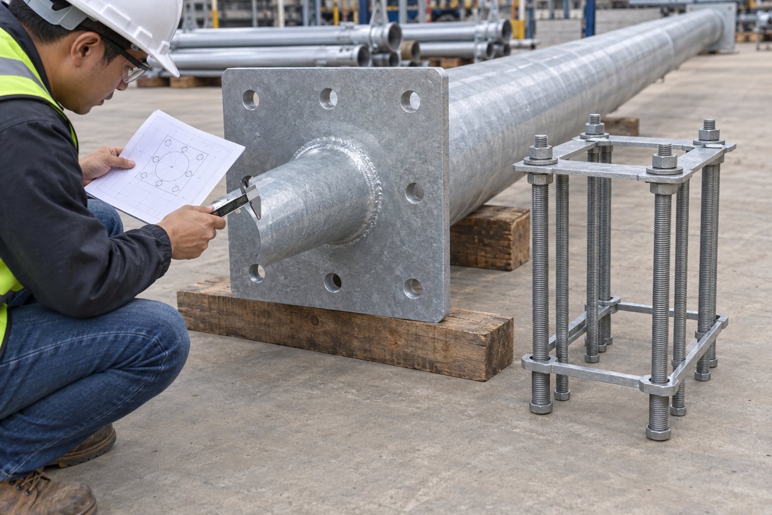
The pole base and civil anchor drawing must use the same geometry.
Issue comments by drawing number, revision, pole mark, location and responsible party. Separate clarification from a design change. For a changed arm reach or fixture, recheck the lighting layout, structural load and foundation reaction; for a shifted door or duct, check access and civil coordination. The owner should identify whether each response is accepted, accepted with a controlled condition, or returned for revision. Production should not run on a superseded PDF that happens to bear an old approval stamp.
| Release item | Evidence required | Release rule |
|---|---|---|
| Pole/location schedule | Marks, coordinates, quantity and drawing cross-reference | Every physical location maps to one current pole type |
| Design basis | Equipment schedule, wind inputs, standard and calculation reference | Drawing and design assumptions agree |
| Interface set | Luminaire, arm, door, flange, anchors, conduit and earthing responsibility | Mating parts and civil/electrical details reconcile |
| Comment log | Response, approver, date and revised callout | No unresolved critical comment or silent deviation |
| Inspection/packing plan | Required records, hold points, marks and shipment sequence | Factory and site can identify each approved part |
This is a document-release checklist, distinct from the geometry matrix. After fabrication, the factory acceptance checklist checks the physical item against the released revision; the installation and erection checklist follows at site.
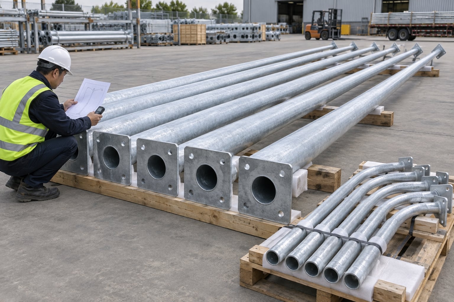
The released drawing is the reference for later physical inspection.
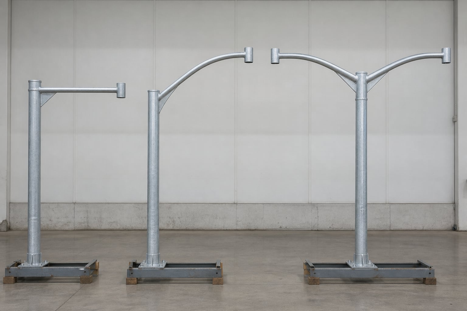
Arm reach and orientation must agree with the selected luminaire and road layout.
For a Jieyao pole inquiry, send the plan/section, pole schedule, actual luminaire and accessory data, site wind basis, foundation responsibility, specified steel and finish, drawing format, inspection requirements and delivery limits. Jieyao can organize the proposed shaft, arm and interfaces for review against those inputs. Final fabrication dimensions and responsibilities are fixed by approved project documents, not this webpage. The steel street light pole range provides a product starting point; contact is the route for the project package.
Only if the location schedule proves the type, equipment, orientation, civil interface and design basis are the same. Otherwise use distinct type marks or exceptions.
Not automatically. The civil designer must use the matching pole reactions, anchor geometry and local geotechnical basis.
The actual fixture or a controlled interface schedule should be identifiable so weight, exposed area, spigot and tilt match the design.
Record the as-built geometry and obtain an engineering disposition. Do not enlarge holes or force a base plate to fit without approval.
A revision-controlled drawing set and closed comment log, linked to pole marks, the accepted design basis and the manufacturing/inspection plan.
Contact Us
Get a custom lighting solution and quotation for your project. Outdoor lighting manufacturer in Yangzhou, ChinaAbout Jieyao LightingYangzhou Jieyao Lighting Equipment Co., Ltd. is an outdoor lighting manufacturer focused on solar street light systems and high mas... Do you have any questions or requests?
Email: jay@jieyaolighting.com

Click to Chat.
Im online now.