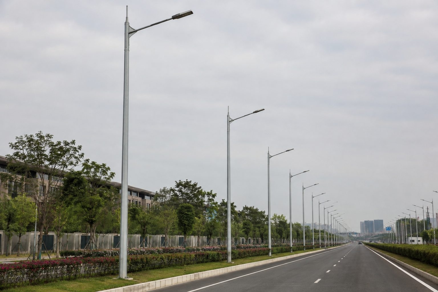


A galvanized street light pole is a steel lighting structure protected by a zinc coating. This guide explains the shaft, bracket, base, access door, hot-dip galvanizing process, inspection points and project information buyers should define before requesting a quotation.
A galvanized street light pole is a fabricated steel support whose exposed steel surfaces receive a protective zinc coating, commonly by hot-dip galvanizing after fabrication. The pole may carry one or more LED roadway luminaires, outreach arms, control equipment and approved accessories. Its structural role is to transfer wind and equipment loads through the shaft, base plate and anchors into a project-designed foundation.
The word galvanized describes the corrosion-protection system, not a complete pole specification. Two poles with the same nominal height can use different steel grades, wall schedules, taper, cross-sections, arm lengths, access openings, base details and wind design criteria. A useful purchase description therefore combines the coating requirement with the mounting height, luminaire data, site wind basis, road geometry and installation method.
Bare carbon steel reacts with moisture and oxygen. Road salt, industrial pollution, coastal exposure, trapped water and damage to a painted surface can accelerate deterioration. Zinc separates the underlying steel from the environment and also provides sacrificial protection at small exposed areas. The performance of the finished system depends on steel preparation, drainage and venting, immersion control, coating continuity, handling and the actual exposure.
Galvanizing should not be described as maintenance-free or assigned one universal service life. The surrounding environment, zinc thickness, wetness, chemicals, soil contact, installation damage and inspection program all matter. The project should state the applicable coating standard and any appearance, repair, duplex-paint or inspection requirements instead of relying on a marketing claim.
A straight or tapered steel tube carries the vertical, bending and torsional actions. Common forms include round and polygonal sections.
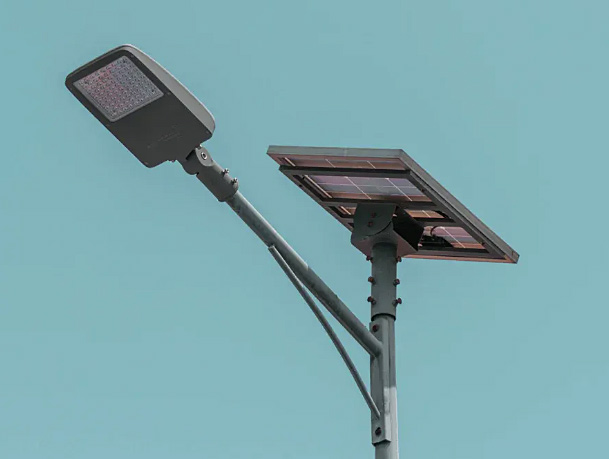
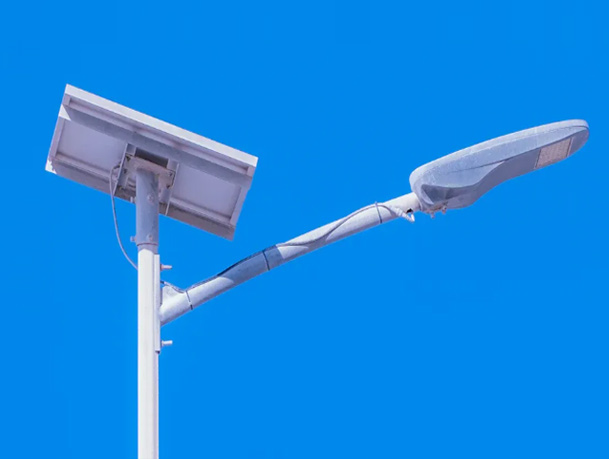
The upper connection positions the luminaire. Reach, rise, tilt, diameter and drilling must match the selected fixture.
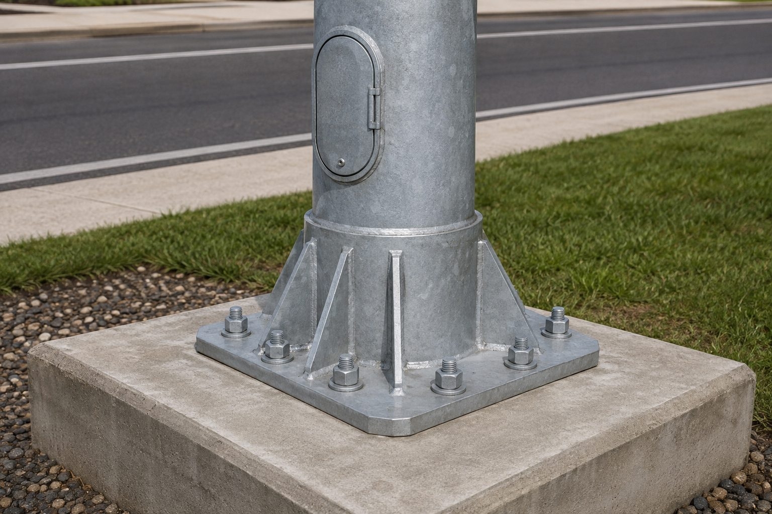
A flange plate, stiffeners where required and anchor bolts connect the pole to the concrete foundation.
An access opening can house terminals, protective devices or cable connections while maintaining the specified structural detail.
Cables pass from the foundation conduit through the shaft to the luminaire, with entry points protected from sharp edges and water.
The zinc coating covers prepared steel surfaces. Optional paint over galvanizing may be used when color or additional protection is required.
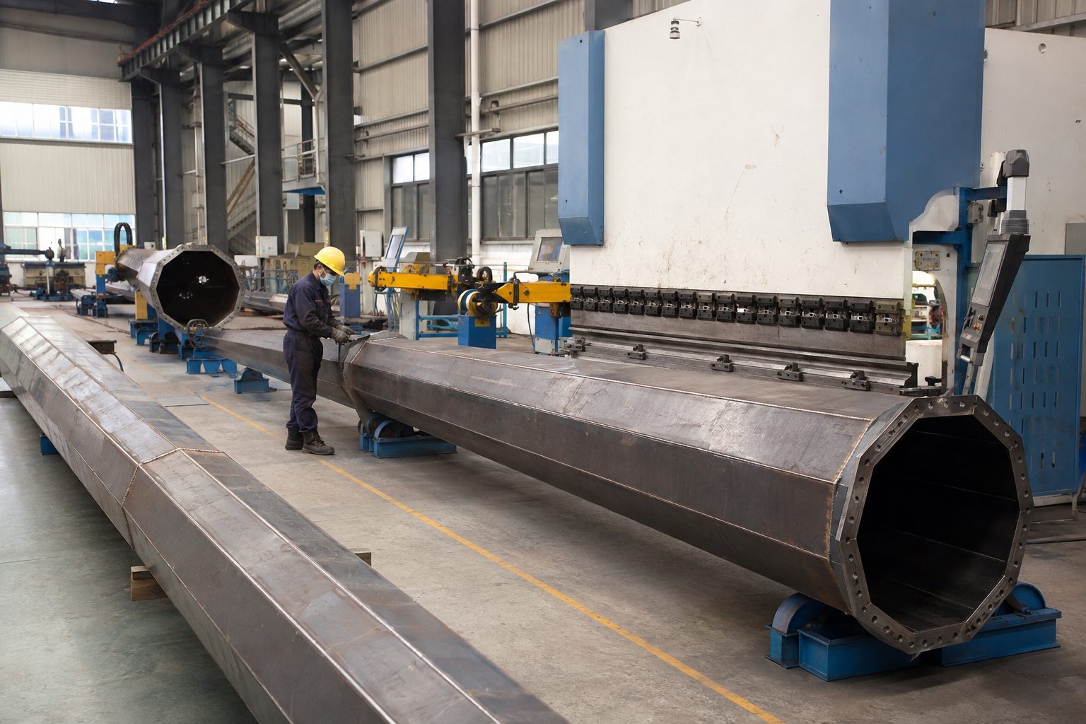
A tapered polygonal shaft usually begins as a steel plate cut to a developed profile. The plate is formed through a press brake or suitable forming equipment, then the longitudinal seam is welded. Round tapered shafts can use different forming methods, while constant-diameter poles may be made from tube. Fabrication planning must account for the plate grade, thickness, taper, seam location, door reinforcement and the dimensional limits needed for assembly.
Weld procedures, inspection scope and acceptance criteria should follow the contract and governing fabrication standard. The pole supplier should not add openings, brackets or attachments after structural design without checking their effects. Door corners, weld terminations and abrupt section changes deserve particular attention because they can influence local stress. Dimensional inspection before galvanizing helps identify straightness, fit-up or interface issues while correction remains practical.
Round shafts offer a continuous appearance and can suit many architectural or utility requirements. Octagonal and other polygonal shafts are common for tapered roadway poles because they can be formed from plate and provide flat faces for controlled fabrication. The choice is not only visual. Available tooling, wall schedule, taper, slip-joint geometry, door orientation and structural calculations all influence the section.
A buyer should avoid assuming that an octagonal pole is automatically stronger than a round pole, or that one shape has a fixed wind capacity. Capacity follows the complete design: outside dimensions, material properties, thickness, openings, connections, unsupported height and applied loads. The approved drawing should state the actual section and dimensions used in the calculation.
Shorter poles are often supplied as one piece when local transport and handling allow. Taller poles or export shipments may use two or more sections to improve container loading and site logistics. Sectional poles can use engineered slip joints or flanged connections. The joint length, profile compatibility, orientation and assembly method must be defined by the supplier.
A segmented pole is not simply a long shaft cut into pieces. The joint changes local geometry and must transfer the design actions. Field crews need clear markings, lifting instructions and engagement requirements. If the design uses a slip joint, the actual assembled overlap should be checked before erection; forcing an incompatible joint can damage the coating or create an unreliable connection.
A base-plated pole stands on a flange connected to anchor bolts cast into a concrete foundation. This arrangement provides a clear interface among pole supplier, anchor-cage supplier and civil contractor. It also allows the pole to be erected after the foundation has gained the required strength. The plate size, thickness, bolt circle, hole diameter, stiffeners and conduit opening must match the approved structural and civil drawings.
A direct-embedded pole extends into the ground or a foundation sleeve instead of using a flange. Embedment depth, drainage, soil or concrete contact, corrosion protection and backfill method become part of the design. The preferred system depends on local standards, maintenance practice and site conditions. A base detail should never be copied between projects without verifying reactions, soil, frost, groundwater and construction requirements.
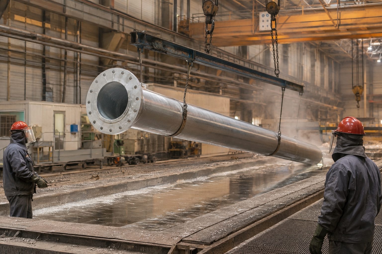
Hot-dip galvanizing is normally performed after cutting, forming, welding and drilling are complete. The fabricated steel is cleaned through a controlled pretreatment sequence that removes oil, scale and oxides. It is then fluxed and immersed in molten zinc using a process suitable for the component and specified standard. Zinc reacts with the steel surface to form alloy layers with an outer zinc layer.
Long hollow poles require planned lifting points, vent holes and drain holes. These openings allow air, cleaning liquids and molten zinc to move safely through enclosed spaces. Their size and position must suit the galvanizer's procedure without compromising the structural detail or allowing water traps in service. After withdrawal, the pole is cooled, inspected and finished where necessary. Handling equipment should protect the coating from deep damage.
The contract should name the standard accepted by the project authority. Depending on market and project, specifications may reference standards such as ISO 1461 or ASTM A123/A123M for hot-dip galvanized fabricated steel articles, together with applicable local requirements. The selected standard defines matters such as coating assessment, sampling and permissible repairs; the purchase order should not combine incompatible clauses without engineering review.
State any additional requirements separately: surface appearance, minimum local or average coating values where permitted, test locations, documentation, repair method, thread treatment, duplex paint, packaging and third-party witness points. Coating specifications should recognize the steel chemistry and component geometry because they can affect zinc growth and finish. Cosmetic appearance and corrosion performance are related but not identical acceptance questions.
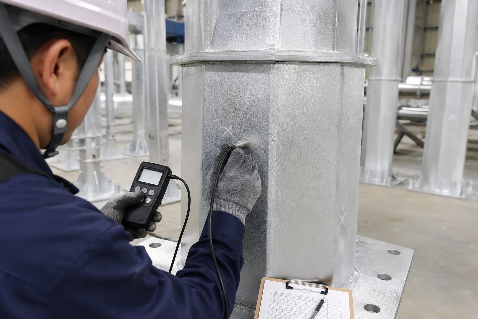
Inspection commonly includes visual examination and magnetic or electromagnetic thickness measurement using calibrated equipment suitable for the substrate and coating. Measurements should follow the referenced standard's sampling method and should be taken on representative areas rather than only at a convenient point. The inspector also checks continuity, drainage, sharp deposits, runs, bare areas and damage that could interfere with assembly or safe handling.
A single gauge reading should not be treated as the result for an entire pole. The acceptance method normally considers several readings within defined reference areas. Buyers should agree whether mill certificates, galvanizing records, inspection reports, photographs or independent witnessing are required. These documents are contractual quality records, not substitutes for a technically complete pole drawing.
Freshly galvanized steel may show bright silver areas, matte gray zones, variations in spangle, minor handling marks or differences around welds. Appearance can change as zinc weathers. These variations do not automatically indicate poor protection. Acceptance should be based on the specified standard and whether the surface is continuous, usable, safe to handle and compatible with mating parts or any subsequent paint system.
Areas with bare steel, heavy deposits that prevent assembly, sharp projections, un-drained pockets or significant mechanical damage require review. Repair, if allowed, should use a method accepted by the governing standard and project specification. Grinding should be controlled so it does not remove sound coating unnecessarily. If architectural uniformity is important, it must be stated before production rather than added after delivery.
| Decision Factor | Hot-Dip Galvanized Steel | Painted Steel | Duplex System |
|---|---|---|---|
| Primary protection | Zinc coating metallurgically bonded to prepared steel | Organic coating system over prepared steel | Paint or powder coating over compatible galvanizing |
| Appearance | Natural zinc finish with normal visual variation | Wide color and gloss choice | Color choice with zinc beneath |
| Damage behavior | Zinc can provide sacrificial protection at small exposed areas | Performance depends on coating continuity and repair | Two compatible protection mechanisms when correctly specified |
| Process timing | Normally after fabrication | After surface preparation, often in multiple coats | Requires compatibility and controlled preparation of galvanized surface |
| Selection basis | Exposure, standard, geometry, handling and inspection | Exposure category, preparation, coating system and maintenance | Severe exposure, appearance or project-specific durability strategy |
No column is automatically correct for every site. Marine air, industrial chemicals, buried zones, decorative color, repair access, lead time and local specification can change the decision. When paint is applied over galvanizing, the surface preparation and coating products must be compatible with the zinc layer.
Chinese production may use grades such as Q235B or Q355 when appropriate to the design and contract. International projects may specify equivalent grades under other standards. Substitution should be based on documented mechanical properties, chemistry, thickness availability, weldability and the governing design method rather than a casual name comparison.
A higher yield strength does not by itself create a better pole. Wall thickness, local buckling, fatigue-sensitive details, deflection, galvanizing behavior, weld procedure and availability must be considered together. The approved bill of materials and drawing should identify the grade actually supplied, and any required material certificates or traceability should be stated in the inspection plan.
Wind design begins with the governing structural code and its wind-speed definition, return period, exposure or terrain category, topographic factors and importance provisions. The pole calculation then includes the projected area and drag characteristics of the shaft, arms, luminaires and every approved accessory. Fixture weight also affects gravity actions and dynamic behavior.
A catalogue statement such as “resists 160 km/h wind” is incomplete without the associated code, exposure, gust definition and equipment area. Cameras, banners, solar panels and signs can add substantial wind demand and torsion. Provide their dimensions, weight, mounting height and offset before design. For a deeper engineering overview, see the wind load and EPA guide for lighting structures.
Nominal pole height may refer to shaft length above the base, luminaire mounting height or another project definition. Bracket rise and road level can create a difference. The drawing should show the agreed reference. Arm reach positions the luminaire relative to the carriageway, while tilt and mounting angle influence the photometric result and wind load.
The luminaire interface should define tenon or spigot diameter, insertion length, bolt pattern, cable entry and orientation. The selected fixture's weight, effective projected area and center of gravity belong in the structural input. The photometric designer should also verify that the installed position matches the calculation file. A mechanically compatible fixture can still produce the wrong road distribution if outreach, tilt or rotation changes.
Height is selected with road width, pole setback, luminaire distribution, target criteria, spacing, glare, maintenance access and structural demand. A 6m galvanized street light pole may suit local streets, paths or smaller public areas. An 8m galvanized street light pole is a common starting point for many urban road layouts.
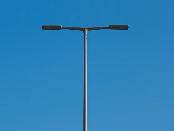
Wider or faster roads may evaluate a 10m single-arm pole, a 10m double-arm pole for a median, or a 12m highway pole. These are procurement categories, not automatic spacing rules. Final quantities and mounting geometry should follow an approved lighting calculation with verified luminaire data.
The service opening provides access to terminals, protective devices or cable connections specified for the project. Its dimensions, height and reinforcement affect both usability and structural capacity. The cover should fit securely, resist expected weather exposure and use an access method acceptable to the owner. Sharp edges and uncontrolled cable contact should be avoided.
Earthing and bonding requirements follow the local electrical design. The pole may include an internal earthing point, terminal provision or mounting rail when shown on the approved drawing. Conduit entries, cable lengths, glands, surge protective devices and disconnect arrangements need clear scope boundaries. The pole supplier should not assume responsibility for site wiring or protective-device coordination unless it is included in the contract.
The pole supplier can provide base reactions and an anchor arrangement for the approved pole and equipment configuration. A qualified local civil engineer then designs or verifies the concrete foundation using soil properties, groundwater, frost, slope, drainage, seismic requirements and construction practice. The anchor-bolt template, bolt circle and conduit opening must agree with the pole base plate before concrete placement.
Common site errors include rotated bolt cages, incorrect projection, missing leveling space, blocked conduits and foundations cast from an unrelated drawing. Early coordination prevents field drilling or forced assembly that could damage the coating and weaken the connection. The erection procedure should define leveling, nut arrangement, grout if required, bolt tightening and inspection under the applicable design.
Galvanized poles are long, relatively slender products. Export packing should prevent uncontrolled metal-to-metal rubbing, protect flanges and threads, separate brackets and small hardware, and suit the agreed loading method. Section lengths and bundle dimensions must fit the selected container or transport route. Packing lists should identify pole sections, arms, anchors and loose components so site teams can assemble complete sets.
Web slings, padded supports and suitable spreader arrangements help reduce coating damage during unloading and erection. Chains or sharp forks should not contact finished shafts without protection. Poles need stable storage above standing water and soil. If damage occurs, it should be assessed against the specified standard and repaired using an approved method before the area becomes inaccessible.
Check concrete readiness, bolt pattern, projection, conduit position and working space.
Match pole sections, arms, anchors and hardware to the packing list and drawing.
Use controlled lifting points and soft slings; assess any damaged zinc before erection.
Confirm slip-joint engagement, arm orientation, fixture interface and cable route.
Set verticality, tighten the base connection and complete grout or sealing where specified.
Verify earthing, circuits, controls, luminaire aiming and the approved lighting scene.
A practical inspection program considers coating condition, water traps, base corrosion, anchor hardware, door security, wiring, bracket connections, luminaire condition, alignment and unauthorized accessories. Frequency depends on exposure, authority practice, traffic risk and project requirements. Areas near the ground, road-salt splash, irrigation, soil contact and dissimilar metals may deserve closer attention.
Cleaning and repair methods should be compatible with zinc. Aggressive grinding, acidic cleaners or uncontrolled paint can create new problems. If structural deformation, cracking, severe corrosion, impact damage or loose anchors are observed, the pole should be assessed by qualified personnel. Maintenance teams should control traffic and work-at-height hazards before accessing the fixture.
Height does not define wall thickness, wind basis, fixture load, arm geometry, base or steel grade.
State the code, wind definition, exposure, topography and accessory EPA.
Foundation design depends on actual pole reactions, anchors, soil and local civil requirements.
Weight, EPA, tenon, tilt and cable interface must match the structural and optical design.
Banners, cameras and solar equipment change wind area, eccentricity and sometimes the foundation.
Name the coating standard, sampling, records, witness points and acceptable repair method.
If information is missing during budgeting, the supplier should state the assumptions and mark them for confirmation. An apparently precise quotation built on hidden defaults creates more risk than a configurable proposal with clear exclusions. Jieyao's street light pole range provides a starting point for project-specific discussion.
A useful general arrangement identifies overall dimensions, shaft sections, material, wall schedule, arm geometry, fixture interface, door opening, cable route, base plate, anchors and corrosion protection. Structural documentation should state the design basis and approved accessory loads. Foundation reactions need to match the exact pole configuration used for production.
Quality records may include material documents, dimensional checks, weld inspection scope, galvanizing inspection, trial assembly and packing lists as required by the contract. The submittal should distinguish routine production controls from project-specific certification or independent inspection. Final manufacture should follow approved drawings and revisions, not only a product-page description.
It means the steel has a protective zinc coating.
No. The purchase specification should state the required process and standard.
Yes, with compatible preparation and a suitable duplex coating system.
The designer selects a suitable grade with the wall schedule and project loads.
Not automatically. Capacity depends on the full section, material and design.
Yes, when the engineered joint and assembly requirements are defined.
The supplier provides reactions; a local civil engineer verifies the foundation.
Provide the code, wind definition, exposure, topography and equipment EPA.
A calibrated coating gauge is used with the specified sampling method.
Send height, road plan, wind basis, luminaire data, quantity and destination.
Send Jieyao the road layout, mounting height, luminaire data, wind criteria, preferred shaft and bracket, base interface, coating requirement, quantity and destination. The resulting proposal can coordinate the pole, arm, base plate, anchors, documentation and packing around the actual project inputs.
Send Pole Requirements and DrawingsContact Us
Get a custom lighting solution and quotation for your project. Outdoor lighting manufacturer in Yangzhou, ChinaAbout Jieyao LightingYangzhou Jieyao Lighting Equipment Co., Ltd. is an outdoor lighting manufacturer focused on solar street light systems and high mas... Do you have any questions or requests?
Email: jay@jieyaolighting.com

Click to Chat.
Im online now.