


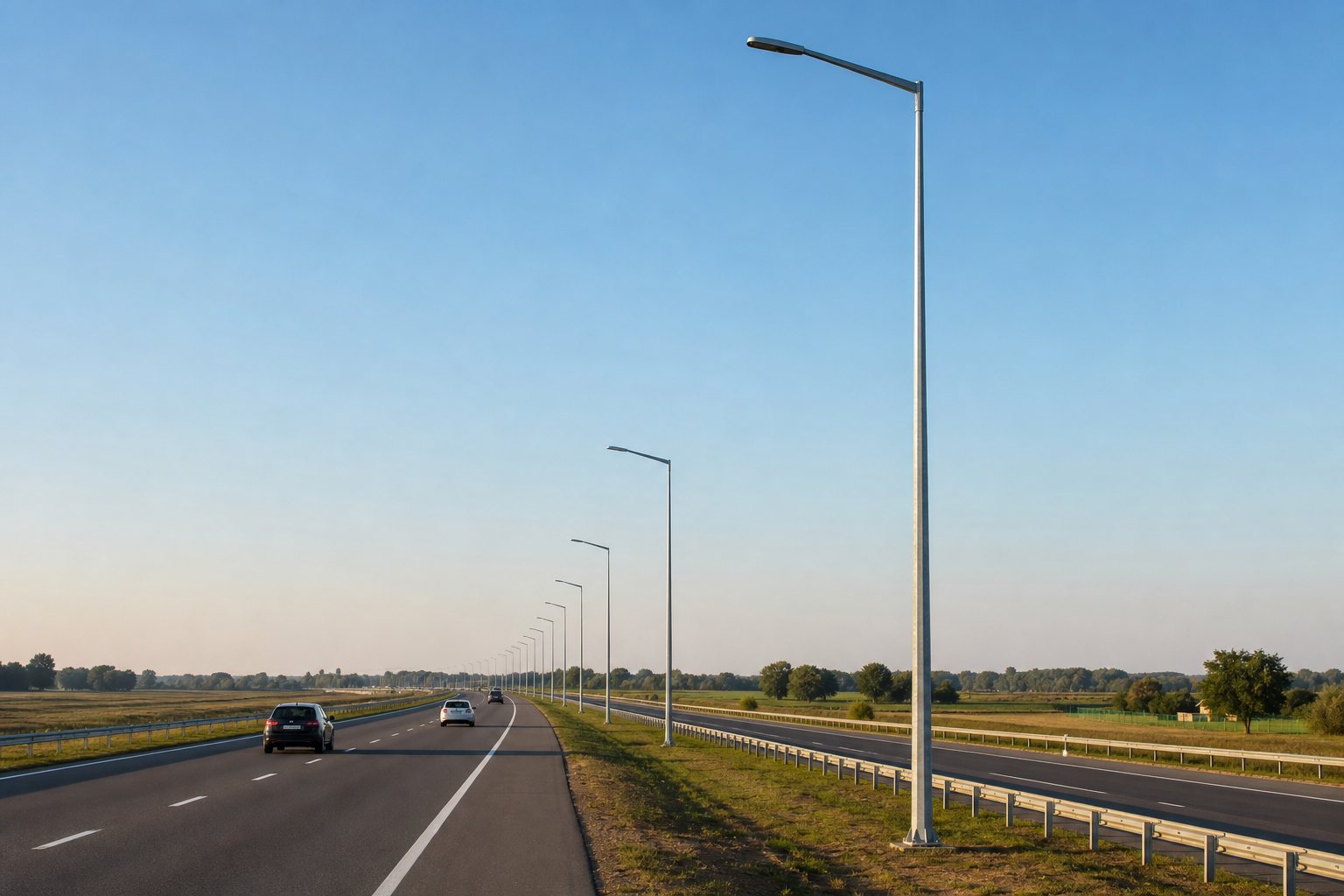
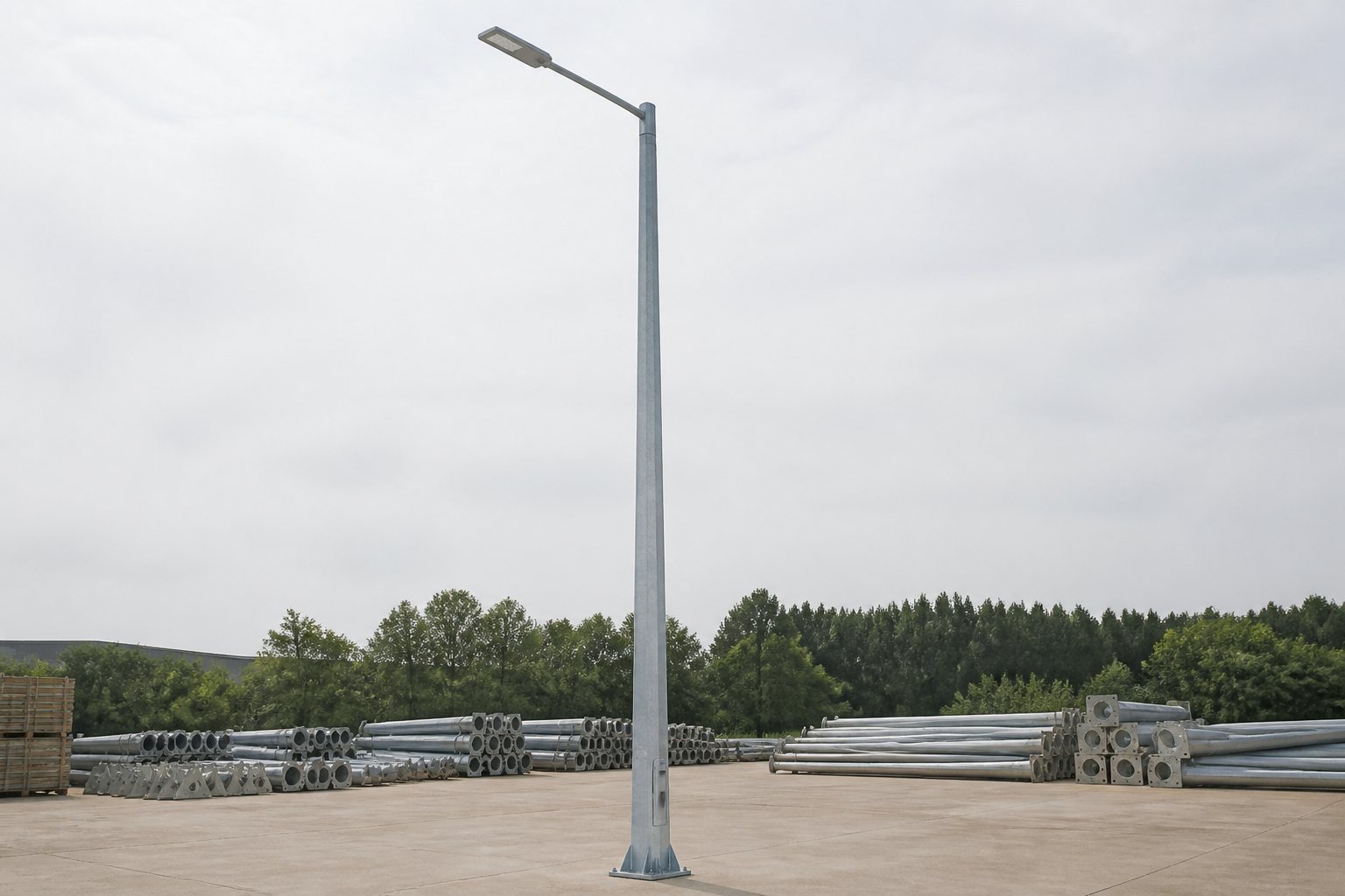
A project-configured 12 meter steel lighting pole for expressways, wide arterial roads, bridge approaches, industrial corridors and transport infrastructure. Shaft geometry, steel grade, arm layout, luminaire load, wind basis, base plate, anchor cage and section length are coordinated from the actual project conditions.
A 12m galvanized street light pole provides a higher mounting position than the poles commonly used on residential or secondary roads. The added height can help roadway luminaires distribute light over wider carriageways and longer pole spacing, but it also increases structural demand, lifting requirements and foundation reactions. A useful specification therefore describes much more than height and nominal wall thickness.
Jieyao develops 12 meter poles around the road geometry, proposed lighting layout, luminaire characteristics, local wind basis, site exposure, foundation interface, surface-protection requirement and transport plan. The pole may use a single arm for roadside installation, a double arm for a central median, or a project-specific bracket for an interchange or bridge approach. A one-piece or segmented shaft can be selected after manufacturing, galvanizing, shipping and site assembly constraints are reviewed.
The dimensions and values on this page are configurable. Production follows an approved drawing and purchase specification. Where local law or the project contract requires structural or civil review by a licensed engineer, the final pole and foundation documents should be checked under those requirements.
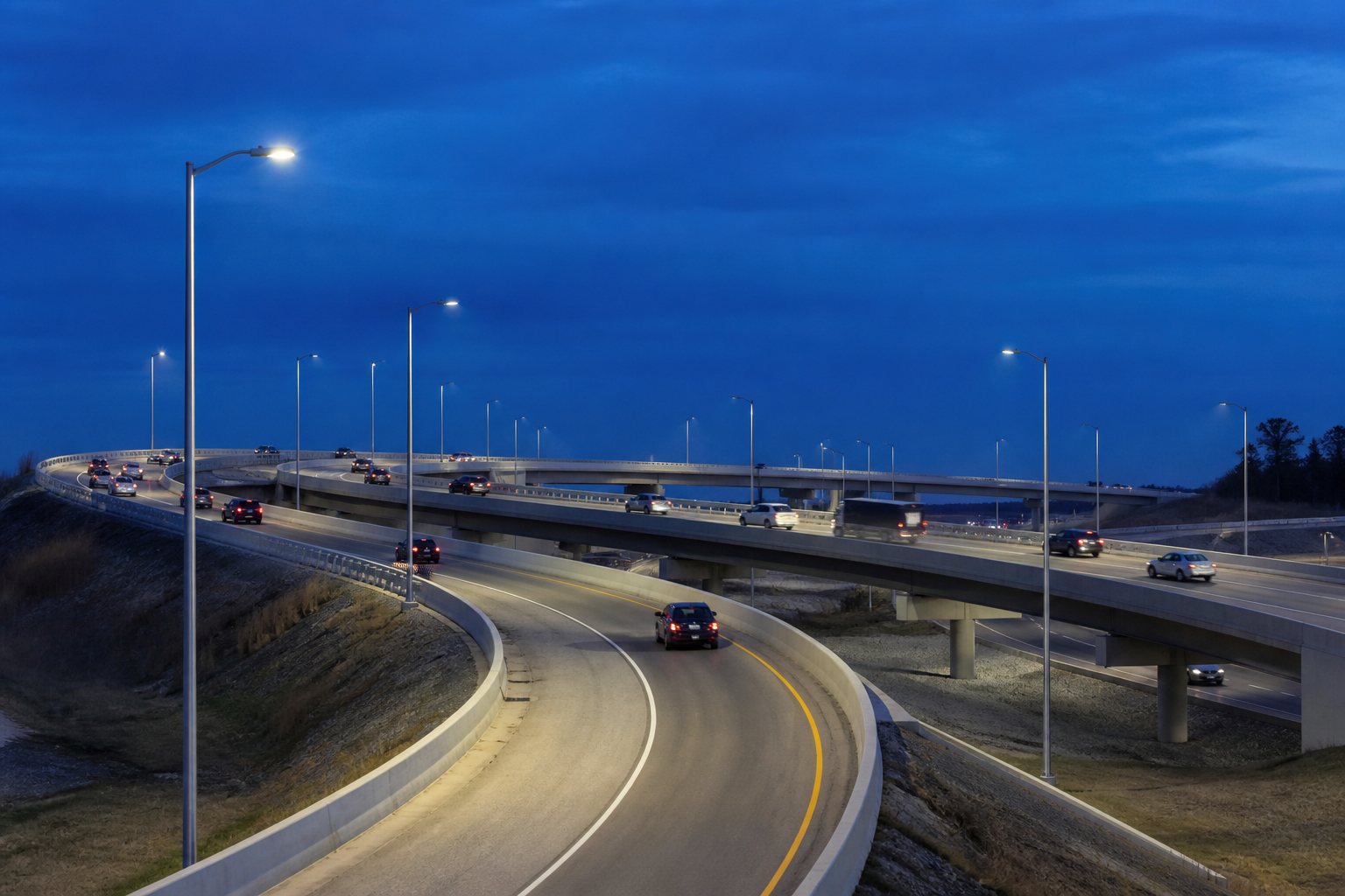
Higher mounting can provide broader optical coverage on mainline sections, ramps and highway approaches. Open terrain may create demanding wind exposure, so the governing standard and fixture EPA must be known.
Multi-lane roads, central medians and major intersections often require coordinated roadside and median pole types. Photometric design determines whether 12m mounting improves uniformity and glare control.
Elevated structures and approach zones may combine stronger wind exposure, restricted base geometry and authority-specific vibration or barrier requirements. These inputs must be reviewed early.
Logistics routes and factory access roads need visibility for trucks, loading entrances and pedestrian conflict areas. Robust coating, protected wiring and clear maintenance access support long-term operation.
Transport facilities may need controlled glare, corrosion-resistant finishes and strict equipment clearances. Coastal air or deicing chemicals can influence the surface-protection plan.
Circulation roads around terminals, stadiums and distribution centers can use 12m poles where the photometric layout justifies wider reach without moving to a high-mast system.
| Item | Available Project Configuration | Decision Basis |
|---|---|---|
| Nominal height | 12m; custom mounting reference available | Define shaft height, mounting height and any arm rise separately. |
| Steel grade | Q235B, Q355 or specified equivalent | Structural demand, specification, availability and material certification. |
| Shaft form | Tapered octagonal or project-defined polygon | Strength, manufacturing method, appearance and slip-joint compatibility. |
| Section construction | One-piece or segmented shaft | Galvanizing bath, transport length, container plan and erection method. |
| Bracket | Single, double or custom arm | Road cross-section, optics, fixture position, EPA and maintenance access. |
| Luminaire interface | Custom tenon and cable route | Fixture weight, projected area, mounting opening and locking method. |
| Surface treatment | Hot-dip galvanized; optional duplex coating | Specified standard, corrosivity, appearance and maintenance plan. |
| Base | Flanged base plate with optional stiffeners | Calculated reactions, shaft geometry and foundation interface. |
| Anchors | Project-specific cage, bolts, nuts and template | Bolt grade, diameter, embedment, projection and civil coordination. |
| Access opening | Lockable reinforced door with earthing point | Electrical equipment, structural detail and safe roadside access. |
| Design wind basis | Defined for the project | Code, speed definition, exposure, topography and importance. |
| Submittals | Drawings, reactions, records and optional calculation scope | Tender requirements and commercial agreement. |
Final dimensions are established by the approved project drawing; the table is not a universal certified pole specification.
Wind, fixture weight and arm reach act through a taller lever than they do on a shorter roadway pole. A heavy luminaire or long bracket near the top can add meaningful bending and torsion. Open highway terrain, bridge decks, coastal roads and elevated approaches may also be more exposed than a sheltered urban street. These effects cannot be represented reliably by height and plate thickness alone.
Structural capacity also depends on steel grade, top and bottom shaft dimensions, taper, polygon geometry, door opening, weld details, section joints, base plate and anchors. A thin but efficiently shaped shaft can behave differently from a thicker shaft with unsuitable geometry or poorly detailed openings. Jieyao therefore confirms the full load path before releasing a wall schedule.
Q235B is commonly used for conventional steel lighting poles because it provides practical forming and welding characteristics. Q355 offers a higher nominal yield strength and may be selected when the structural design, tender document or material-efficiency objective supports it. A higher grade does not remove the need to check local buckling, openings, welds, fatigue-sensitive details, base behavior and corrosion protection.
International projects may specify EN, ASTM or other material systems. Any proposed equivalence should be reviewed against mechanical properties, chemical composition, forming and welding requirements rather than matched by name alone. Material records for the order should correspond to the plate actually used in production.
A tapered polygonal shaft places more section capacity near the base, where bending demand is usually higher, and reduces diameter toward the luminaire. The shape is produced from developed steel plate using press-brake forming and a longitudinal seam. Octagonal geometry is common for roadway poles, while other polygon counts may be used when design, tooling or specification requires them.
Important drawing dimensions include length, top and bottom width across flats, taper, wall schedule, number and position of sections, and orientation of the seam, door and arm. For segmented shafts, the mating profiles and joint location must be compatible. A product photograph cannot communicate these controlled values.
A one-piece pole simplifies site assembly and avoids a shaft slip joint, but its transport and galvanizing requirements can be restrictive. Route permits, trailer length, container dimensions, factory handling and available galvanizing bath length may affect feasibility. A segmented design divides the shaft into pieces that are easier to pack and move but introduces a designed field joint.
Section length should be coordinated before the drawing is approved. Cutting a completed design at an arbitrary location can change geometry and joint behavior. The joint should sit where the tapered profiles can develop the required engagement and where installers can assemble the pole using available equipment. Packaging efficiency must be balanced with site labor and quality control.
The slip joint connects nested tapered sections through controlled overlap and contact. Required engagement depends on the design and geometry. The shop drawing should show the nominal overlap, assembly marks, section orientation and any specified pulling or pressing procedure. Sections should fit without uncontrolled hammering that could deform the shaft or damage the zinc coating.
Trial fitting or profile checks can be performed before galvanizing. At site, the mating surfaces should be inspected for damage, heavy contamination and obstructions. Sections are supported in alignment, pulled together using the approved method and checked for overlap and straightness. The completed shaft is then prepared for arm and luminaire installation according to the lifting plan.
A roadside 12m pole often uses one arm to position the luminaire above the target carriageway. Median poles may carry two equal arms for opposing lanes. Intersections, service roads or asymmetrical medians can require unequal outreach or different luminaire aiming. The bracket layout should follow the photometric design rather than a standard decorative shape.
Longer arms increase bending moment and exposed area. Curvature, rise, mounting angle, tube size, connection detail and cable route must be defined. Removable arms can support shipping and replacement but need a reliable mechanical connection and corrosion-protected fasteners. Welded arms reduce loose parts but may increase the shipping envelope.
Luminaire wattage does not define the mechanical interface. The pole supplier needs fixture weight, effective projected area, center of gravity, mounting opening, required tenon diameter, insertion depth, locking bolts, tilt range and cable path. These details influence arm design, wind demand and installation.
Where several luminaire models are being evaluated, the pole can be checked against the most demanding approved fixture envelope. The final chosen model should still be confirmed before arm production. Field drilling, oversized adaptors or improvised clamps can damage galvanizing, alter alignment and create unreviewed loads.
A statement such as “designed for 160 km/h” is incomplete unless the wind standard and definition are given. Codes may use different averaging periods, return periods, gust factors, load factors and importance levels. The same numerical speed can therefore produce different design pressures. Terrain, building shielding, open water, embankments and escarpments also influence exposure.
The inquiry should identify the governing code, basic wind speed, exposure or terrain category, topographic factor and any bridge or authority-specific requirement. If information is not available, the proposal can state preliminary assumptions for review, but production should not proceed with hidden or ambiguous wind criteria.
Effective projected area describes how a luminaire or accessory contributes to wind loading. Shape and drag matter as well as outline area. Two fixtures on a double arm, a camera, traffic sign, banner or communication device can substantially change forces at the top of a 12m pole. The combination should be checked, not just each item separately.
Future accessories should not be added automatically after installation. Asset owners should retain the approved load basis and request a structural review before mounting new equipment. Even a lightweight panel may have a large wind area and can introduce torsion or fatigue-sensitive vibration.
Bridge-mounted poles may face strong and turbulent wind, vibration from traffic, limited base dimensions, barrier interfaces and strict authority requirements. The supporting deck or parapet must be capable of receiving pole reactions. Anchor details may be constrained by reinforcement, waterproofing, prestressing ducts or access below the deck.
The bridge designer should provide the permitted base envelope, attachment concept, dynamic or fatigue provisions, wind basis and any requirements for breakaway behavior or electrical bonding. Jieyao can coordinate the pole geometry and reactions, but the bridge connection must be reviewed as part of the complete structure. A conventional ground-foundation detail should not be copied onto an elevated deck.
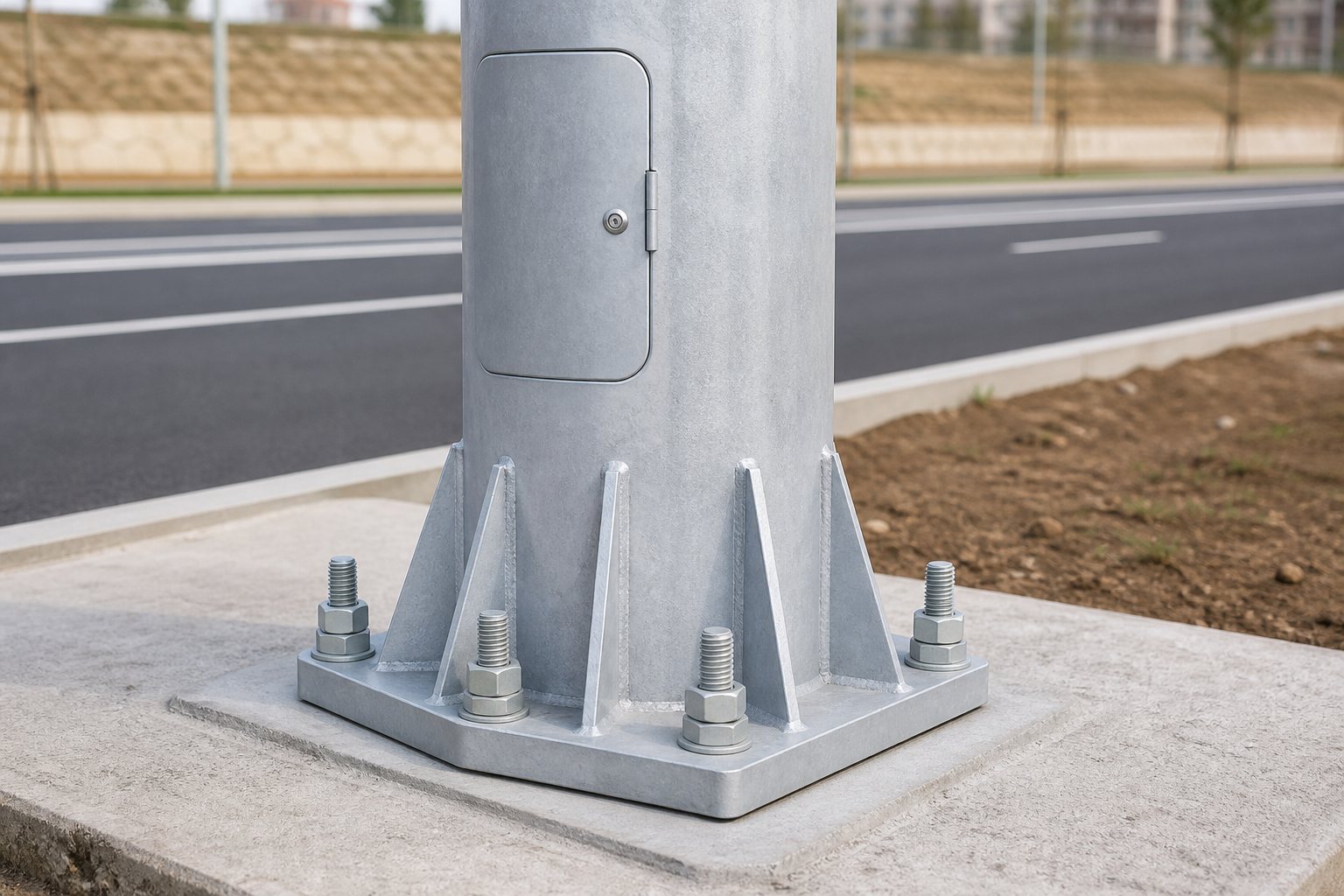
The base plate transfers axial, shear, bending and torsional actions from the shaft to the anchors and concrete support. Outside dimensions, thickness, central cable opening, bolt holes, stiffeners, shaft weld and edge distances are coordinated with the calculated reactions and installation space. An oversized hole pattern or weak local detail can undermine an otherwise adequate shaft.
The drawing should define whether the pole bears directly, uses leveling nuts, uses approved shims or receives non-shrink grout. A large unsupported gap beneath the plate should not be created without an engineered detail. Drainage and corrosion protection around the base also need consideration, especially where deicing salts, standing water or coastal spray are present.
Anchor diameter, grade, length, embedment, projection, thread, nuts, washers and bolt circle are project-specific. A rigid template keeps the cage aligned during reinforcement work and concrete placement. The conduit route must pass through the base opening without conflicting with bolts or reinforcement.
For new foundations, the pole base should be approved before concrete is cast. For existing foundations, the buyer should provide a verified as-built survey with bolt centers, diameter, projection, orientation and photographs. The foundation capacity and condition must also be checked; matching the hole pattern alone does not prove structural adequacy.
Jieyao can provide the actions at the pole base and an anchor arrangement for the supplied pole. The final concrete foundation depends on soil bearing, lateral resistance, groundwater, frost, slope, drainage, concrete and reinforcement properties, nearby utilities and local civil rules. A qualified local engineer should use the site information and pole reactions to design or verify the foundation.
Reference foundation sketches can help coordination but should not be treated as universally applicable. Highway projects may have compacted fills, embankments, retaining structures or restricted shoulders that require special evaluation. Early exchange between the pole, civil and electrical teams reduces late site changes.
The service opening allows technicians to reach terminal blocks, protection devices, cable joints or control equipment. Because the opening removes part of the shaft wall, the size, corner shape, frame and reinforcement are structural details. A close-fitting lockable cover helps protect the equipment from weather and unauthorized access.
Door orientation should avoid live traffic where practical and remain accessible after barriers, landscaping or cabinets are installed. The drawing can include an internal earthing lug, mounting rail and cable-protection features. Equipment scope, voltage and wiring standards should be defined by the electrical specification.
Hot-dip galvanizing forms a bonded zinc coating on prepared steel surfaces and provides sacrificial corrosion protection. Hollow poles require designed vent and drain openings so cleaning solutions and molten zinc can flow safely. Closed cavities, trapped liquid and unsuitable overlap details must be avoided before the fabrication reaches the galvanizing processor.
Coating thickness and acceptance should reference the specified standard and material category. Surface color and zinc pattern can vary with steel chemistry, cooling and handling, so decorative uniformity should not replace performance-based inspection. Threads, slip joints and mating surfaces need controlled finishing so the pole can still be assembled.
Jieyao coordinates galvanizing through a qualified external processor rather than claiming ownership of the galvanizing bath. The pole-supply quality plan still covers vent design, handling, inspection, permitted repair and protection for shipment.
Powder coating over galvanizing can add a specified color and an additional barrier layer. It may be selected for urban appearance, airport or port roads, coastal exposure, or project branding. The system requires suitable preparation of the galvanized surface, compatible pretreatment and powder, controlled curing, thickness checks and a repair method.
Environmental classification, splash or chemical exposure, abrasion and maintenance expectations should be provided. No single coating system guarantees a universal service life. Design details that retain water or damage the coating during installation can shorten performance even when the material specification is strong.
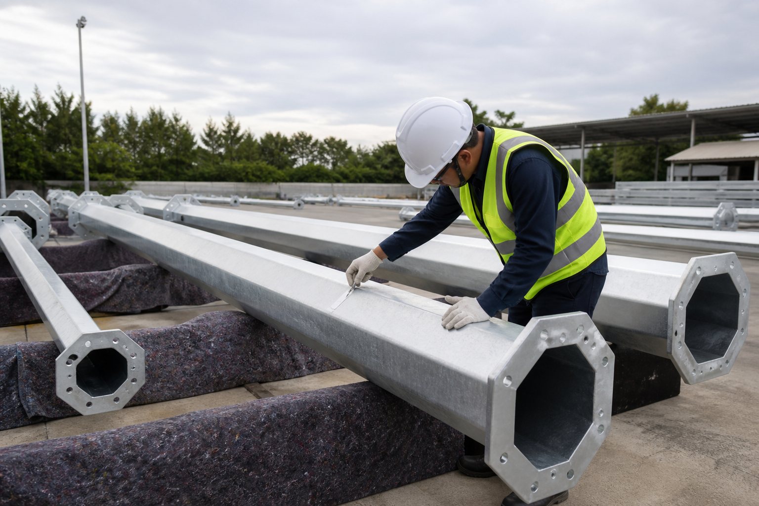
Longitudinal seams, base connections, stiffeners, door frames and arm details require controlled fit-up and welding. Suitable procedures and consumables are selected for the steel grade and joint. Fabrication checks include plate identity, developed dimensions, alignment, weld size, straightness and distortion.
The inspection plan should state the applicable acceptance basis and any required nondestructive examination. UT, MT or other methods are not automatically included for every catalogue pole; their locations, extent, procedure and reporting should match the tender or purchase specification. This keeps the quality scope clear and auditable.
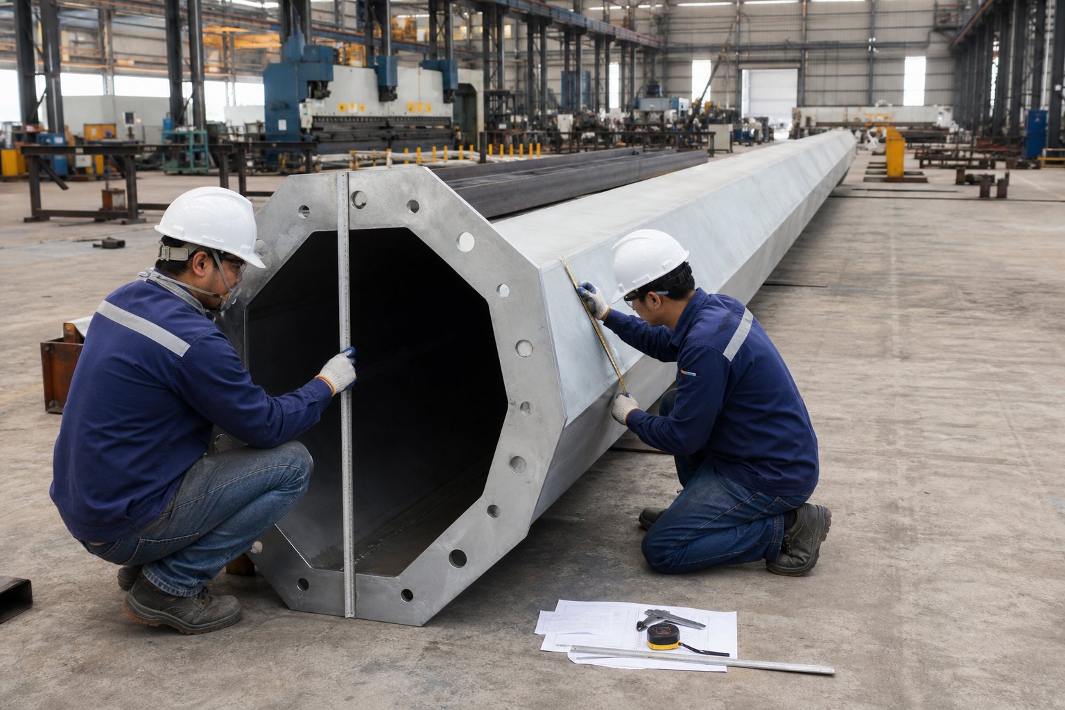
Dimensional checks are performed before coating because major correction becomes more difficult afterward. The team verifies shaft length, top and bottom sizes, taper, straightness, arm orientation, tenon, door position, base holes and cable opening. Vent and drain paths are also reviewed.
Segmented poles can be trial fitted or checked using the approved production method. Match marks and section identification help preserve orientation through galvanizing and packing. Critical dimensions for existing foundations or specified luminaires receive particular attention.
After galvanizing, inspection reviews coating coverage, drainage areas, sharp projections, handling damage, threads, door operation and surfaces that affect slip-joint assembly. Permitted repair methods follow the agreed standard. If powder coating is included, color, appearance and specified test points are checked under the quality plan.
Arms, bolts, templates, doors and electrical accessories are counted against the packing list. Identification should match the drawing type code, especially where single-arm, double-arm, bridge and median poles share one shipment.
Overall reference height, shaft sections, arm geometry, luminaire interface, door and main dimensions.
Steel grade, polygon sizes, taper, wall schedule, section lengths and slip-joint engagement.
Base plate, stiffeners, welds, bolt circle, anchor cage, projection and cable opening.
Agreed wind and load basis, foundation reactions and calculation scope when included.
Material, dimensional, coating and other inspection documents required by the order.
Section assembly, lifting, base connection, grounding, handling and inspection guidance.
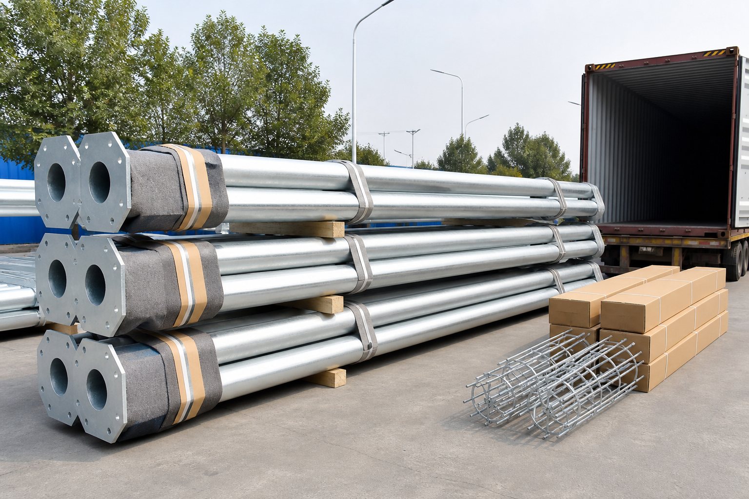
Twelve-meter poles require early logistics review. One-piece shafts may need open-top equipment, special trailers or route permits, while segmented poles can fit standard container plans more readily. The packing design considers section length, nesting geometry, bundle weight, lifting access and destination unloading equipment.
Contact points are protected to reduce coating abrasion. Arms, anchor bolts, templates, doors and loose hardware are packaged so quantities can be checked. The packing list separates pole types and accessories, and package identification follows the approved drawing references.
Long pole sections need stable supports and appropriate restraint. Bare chains or steel bands should not bear directly on finished surfaces without protection. On site, bundles are stored above ground on level supports, away from standing water, mud, chemicals and uncontrolled vehicle movement.
Before assembly, installers confirm package identity, inspect for transit damage and verify that foundations, anchors, cranes and electrical materials are ready. Damaged coating is repaired using the approved method before inaccessible joints are closed.
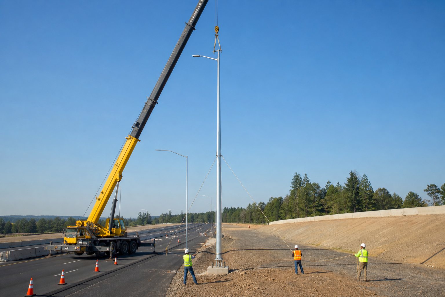
Highway installation requires a project-specific traffic plan, qualified lifting personnel and controlled work zones. Crane capacity, ground bearing, outrigger position, wind condition, rigging certification and lift radius are checked before erection. Workers should not stand beneath a suspended pole or within an uncontrolled swing area.
Median and shoulder installations may require lane closures, barriers and coordination with road authorities. Electrical isolation and underground-service checks are also part of safe preparation. The pole supplier’s guidance does not replace the site contractor’s lift plan and legal responsibilities.
The finished pole should be plumb and the arm aimed according to the road and lighting layout. The installation detail may use leveling nuts, approved shims or grout, but the method must provide the intended base support. Excessive unsupported space beneath a base plate should not be improvised.
Anchor threads are kept clean and protected. Nut tightening follows the project procedure and bolt condition. The owner may require a recheck after grout curing or a defined period of service. Drainage and corrosion protection around the base should remain intact.
A 12m mounting height can support wider spacing in some layouts, but no universal spacing multiplier guarantees compliance. Road width, lane count, pavement reflectance, luminaire distribution, setback, arm outreach, tilt, traffic class, curves, intersections and glare criteria affect the result. Average illuminance alone is not enough; uniformity and visibility matter.
The lighting designer uses the selected luminaire photometric file and an accurate road model to evaluate alternatives. Structural pole design then follows the approved fixture and bracket. Coordinating optics and structure prevents a late luminaire change from invalidating the wind or arm design.
| Factor | 8m Pole | 10m Pole | 12m Pole |
|---|---|---|---|
| Common environment | Secondary and municipal roads | Main roads and industrial corridors | Wide arterials, highways and approaches |
| Optical reach | Moderate coverage with closer spacing | Broader roadway coverage | Potentially wider coverage with suitable optics |
| Wind and base demand | Lower relative demand | Higher and project-specific | More demanding; exposure becomes critical |
| Transport | Often straightforward | One-piece or segmented review | Early section and route planning important |
| Erection | Smaller lifting equipment may be possible | Crane commonly used | Controlled crane lift and larger work zone |
| Selection rule | Choose from photometric, structural, civil, maintenance and lifecycle requirements—not height preference alone. | ||
Buyers can compare the 8m galvanized pole, the planned 10m double-arm pole and this 12m highway configuration as a height cluster. The best choice is the lowest total project solution that meets lighting, safety and maintenance requirements.
The approval drawing should show the exact height reference, shaft segments, polygon dimensions, taper, steel grade, wall schedule, slip-joint engagement, arm geometry, tenon, access door, base plate, stiffeners, anchor cage, conduit opening and finish. Critical interfaces with existing foundations, bridge bases or luminaires should be dimensioned explicitly.
Reviewers compare the drawing with the lighting calculation, road and civil plans, luminaire datasheet, tender schedule and shipping constraints. Type codes should separate roadside, median, bridge and intersection poles. Production begins from the approved revision, and later changes are handled through documented revision control.
The lowest pole unit price is not always the lowest installed or lifecycle cost. Steel weight influences the purchase price, but foundations, anchor cages, road closures, cranes, inland transport, container utilization, coating repairs, electrical access and future maintenance can be equally important. A design that saves a small amount of steel but requires special transport or repeated coating repair may create a higher total cost for the asset owner.
Photometric optimization can affect lifecycle cost by changing the number and location of poles. Fewer poles may reduce foundations and cabling, but excessive spacing can harm uniformity or require higher-output luminaires. Taller poles can broaden coverage, yet they increase structural and erection demand. The practical objective is a coordinated road-lighting solution that meets performance and safety requirements with a maintainable quantity of poles, not simply the tallest or lightest shaft.
Procurement teams should compare offers using the same technical basis. Differences in wind assumptions, luminaire EPA, steel grade, coating system, anchor scope, drawings, testing and packing can make two prices appear comparable when the supply scopes are not. A normalized bid comparison helps expose those differences before award.
Highway tenders often combine civil, electrical, lighting and structural requirements in separate documents. The pole schedule may state height and arm type while another section defines wind code, galvanizing, material testing, drawings or inspection. Jieyao reviews the available documents together and records any conflicts or missing inputs in the technical deviation or clarification list.
The agreed submittal register should identify document titles, review sequence, language, file format and approval responsibility. Long-lead material should not be purchased against an unresolved drawing when anchor patterns, section lengths or steel grade may still change. Likewise, foundation construction should wait for the approved base interface. Coordinated release points reduce rework between factory and site.
Where a third-party inspector or project consultant is involved, hold and witness points should be agreed before production. The inspection scope may include material verification, dimensions, weld review, galvanizing records, coating checks, trial assembly or packing. Clear notice periods and acceptance criteria prevent delay and avoid assuming that every test applies to every pole.
A complete offer states the design basis, steel grade, shaft geometry, wall schedule, arm and fixture interface, base and anchors, finish, documentation, packing and exclusions. It identifies missing inputs instead of hiding assumptions. Buyers should compare the clarity and buildability of proposals, not only unit weight or price.
Useful evaluation evidence includes relevant drawings, material documentation format, fabrication and coating inspection plans, galvanizing arrangement, packing concept and response to deviations. Buyers can also confirm which calculations, NDT, third-party inspections and tender forms are included. This avoids discovering scope gaps after award.
Road authorities should include poles in a risk-based inspection program. Reviews may cover plumbness, vehicle impact, anchor condition, base drainage, door security, coating damage, luminaire alignment, unauthorized equipment and evidence of movement at section joints. Frequency depends on environment, traffic exposure, regulations and asset-owner policy.
Maintenance teams establish traffic control and electrical isolation before approaching or opening a highway pole. Significant deformation, cracking, loose anchors, joint movement or corrosion loss should be evaluated by qualified personnel rather than concealed with a cosmetic repair. Retaining approved drawings, foundation records and inspection history supports future decisions.
It must be defined on the drawing. Arm rise and fixture position are shown separately.
Yes, when the project-specific structural design supports it.
Q355 may be selected for higher structural demand or tender requirements.
Yes. Joint geometry and overlap are defined on the approved drawing.
It depends on the shaft profiles and design. The drawing states the required engagement.
Roadside poles often use one arm; median poles may use two. The lighting layout decides.
Capacity depends on the code, wind speed, exposure, luminaire EPA and accessories.
They can be supplied as part of the approved pole package.
We provide reactions and a reference arrangement. Final design uses local soil data.
Possibly, after an as-built survey and foundation-capacity review.
Yes, only when their loads and positions are included in the structural design.
Yes. A compatible color coating can be applied over galvanizing.
Drawings, material records, inspection reports and packing lists are available as agreed.
Send road drawings, quantity, wind basis, luminaire, arm, finish and delivery details.
Review the general street light pole range for available shaft and finish options. The street light pole height guide explains the optical and project-cost relationship, while What Is a Galvanized Street Light Pole? supports corrosion-protection decisions. These resources should be linked with the 8m, 10m and 12m product pages as one technical cluster.
Send the road cross-section, pole schedule, luminaire datasheet, wind basis, arm arrangement, coating requirement, foundation status, quantity and destination. Jieyao will organize the open technical points and prepare a project-specific 12m galvanized street light pole proposal for review.
Send Project Requirements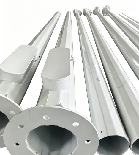
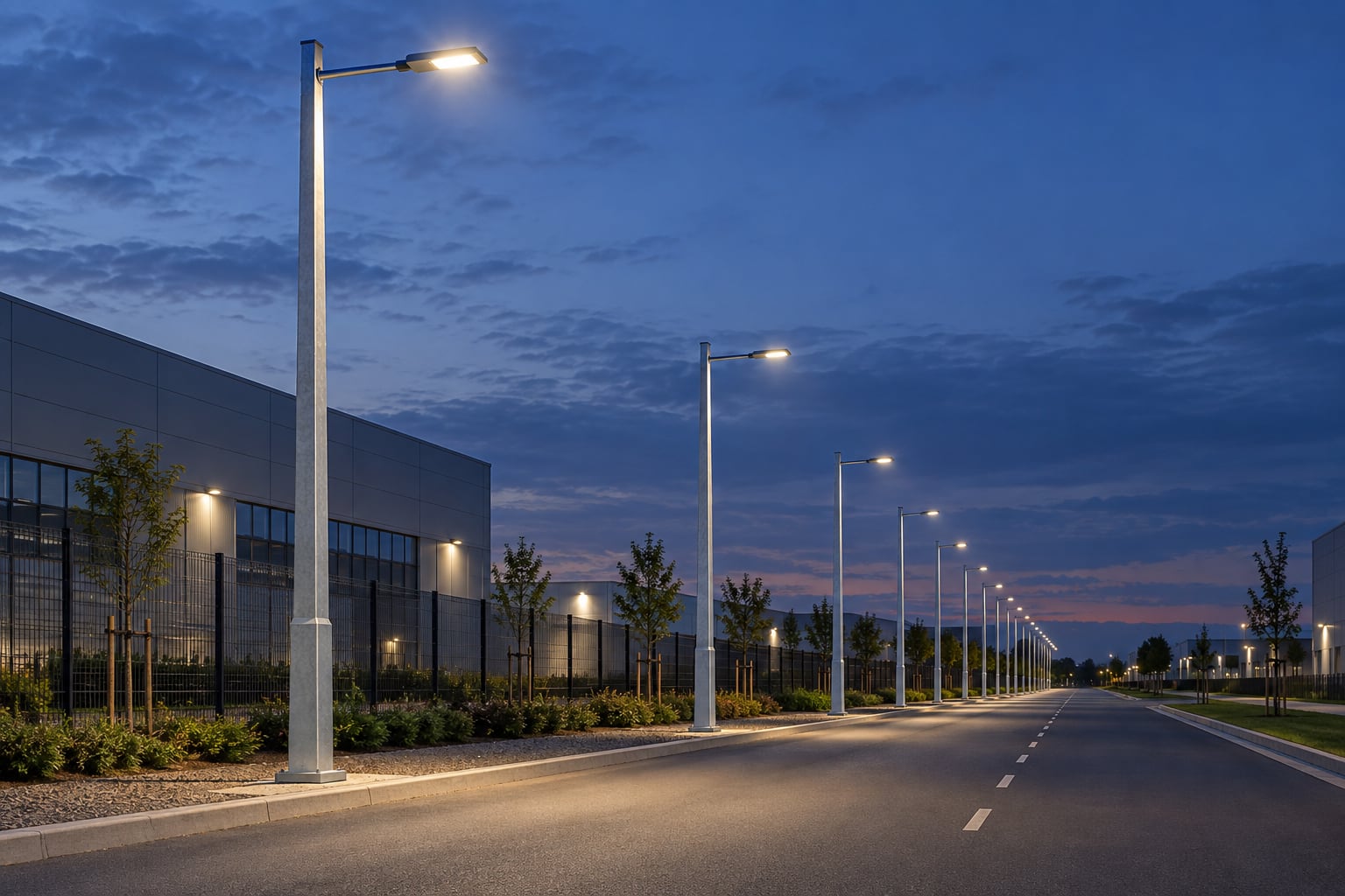
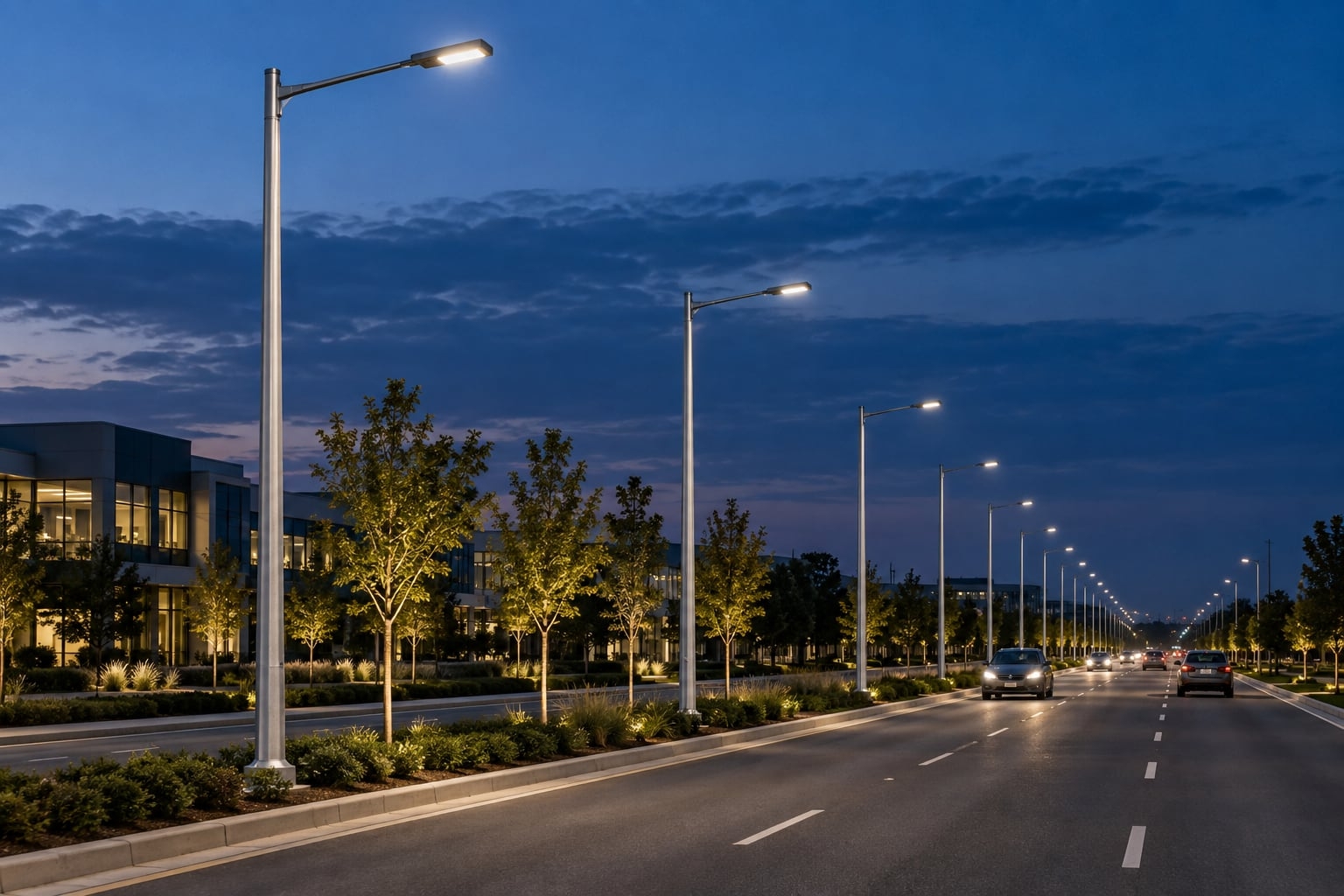
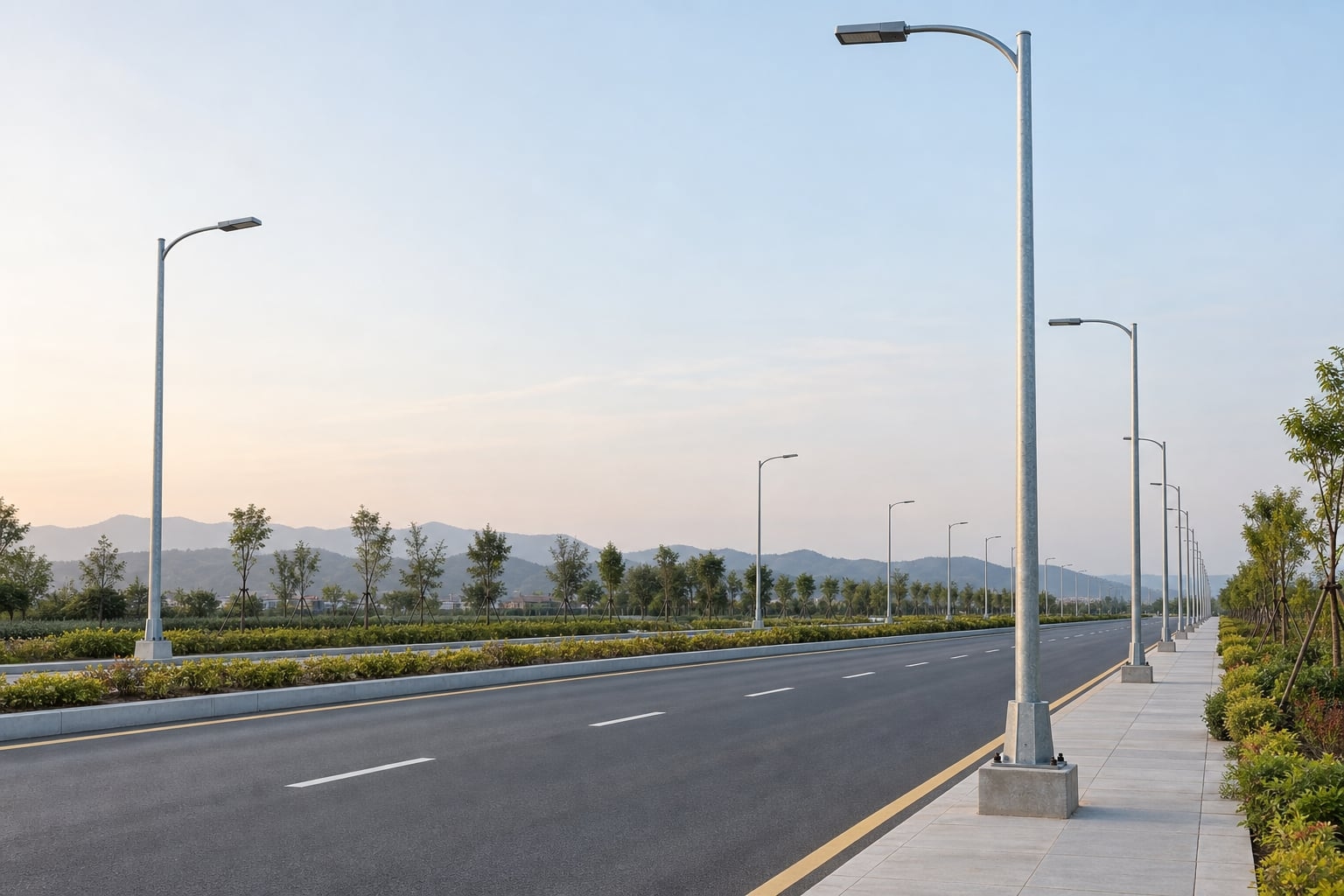
Plan a parking lot light pole layout with photometric files, protected pole locations, glare control, structural loads, foundations and maintenance access. Height and spacing are project-specific.
Learn how to choose lighting poles for airports and ports. Understand key selection standards including wind load resistance, corrosion protection, pole height, material choice, and safety requirements for aviation and marine environments.
Compare hot-dip galvanizing, direct-to-steel paint and compatible duplex coatings for street light poles by exposure, detailing, inspection and repair scope.
Compare galvanized steel, aluminum and stainless steel light pole assemblies by structural design, fabrication, corrosion control, finish, handling and inspection evidence. Select materials for the project exposure and approved supply scope.
Compare single arm and double arm street light poles for roads, highways, parking areas, and municipal projects. Learn the differences in lighting coverage, installation cost, application scenarios, and how to choose the right street light pole for long-term project performance.
The best pole for solar street lights depends on wind load, environment, and project scale. Learn when to choose steel, aluminum, or galvanized steel poles for different outdoor lighting applications.
Discover the life expectancy of street light poles based on materials like steel, aluminum, and concrete. Learn how climate, installation quality, and maintenance affect pole lifespan in real outdoor lighting projects.
Learn how to install a solar street light with pole step by step, including foundation construction, pole erection, wiring, and system testing. A practical guide for road lighting, parking lots, and outdoor solar lighting projects.
We primarily use high-strength carbon steel (Q235/Q345/ASTM A36). We also offer premium aluminum alloy and stainless steel poles specifically for coastal regions.
Tapered poles are aesthetic with low wind resistance; cylindrical poles are more cost-effective; polygonal poles (usually 8/12/16 sides) offer the highest structural strength, ideal for high mast lighting.
Our engineers perform mechanical calculations based on your local wind speed data, adjusting wall thickness and base design to ensure the poles can withstand winds up to 160km/h.
It typically ranges from 3mm to 12mm, depending on the pole height, weight of the fixtures, and local wind load requirements.
This is an anti-corrosion process of immersing steel in molten zinc. It provides over 25 years of maintenance-free rust protection in standard outdoor environments.
Yes. We provide complimentary foundation reference drawings, including concrete depth, rebar specs, and bolt positioning data.
We follow AWS welding standards and use Ultrasonic Testing (UT) or Magnetic Particle Testing (MT) to ensure welds are free of pores or cracks.
We hold ISO 9001 (Quality), ISO 14001 (Environmental), and CE certification (EN 40) specifically for the European market.
Yes. We can produce sample poles for craft and color confirmation, though sample shipping costs are typically covered by the client.
Steel poles are lighter, easier to transport and install, have a long lifespan after galvanization, and offer high scrap value, making them more eco-friendly.
Galvanized poles are virtually maintenance-free. We recommend checking anchor bolt tightness and the powder coating surface every 3-5 years.
We provide touch-up paint with each shipment. Simply clean the scratch and apply the paint to restore the appearance.
No. Base plate size and hole spacing are designed based on pole height and stress loads. We provide detailed dimensional drawings for each order.
These are accessories (like anti-climb spikes) installed on the lower section of the pole to prevent unauthorized climbing and enhance security.
Yes. We can flexibly adjust section lengths (e.g., 6m+6m or 5m+7m) based on logistics constraints and on-site installation conditions.
Contact Us
Get a custom lighting solution and quotation for your project. Outdoor lighting manufacturer in Yangzhou, ChinaAbout Jieyao LightingYangzhou Jieyao Lighting Equipment Co., Ltd. is an outdoor lighting manufacturer focused on solar street light systems and high mas... Do you have any questions or requests?
Email: jay@jieyaolighting.com

Click to Chat.
Im online now.