
Use the required light positions to choose the arm arrangement. Two individual arms and a shared crossarm can sometimes place two luminaires at the same points. They can also produce very different layouts despite carrying the same number of lights. Compare the positions and aiming directions first, then the support connections, loads and installation access.
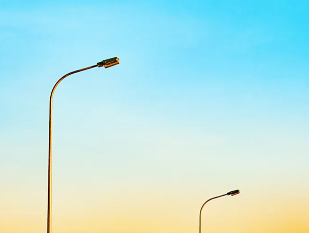
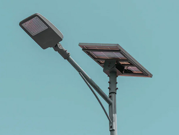
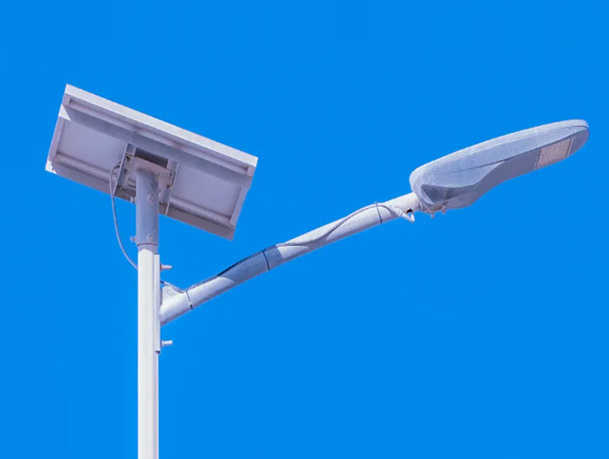
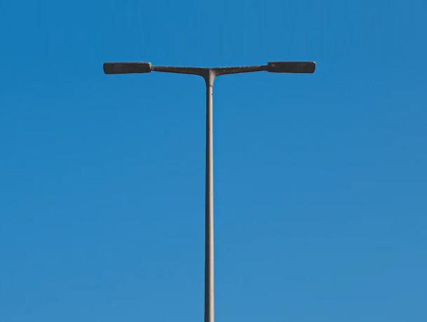
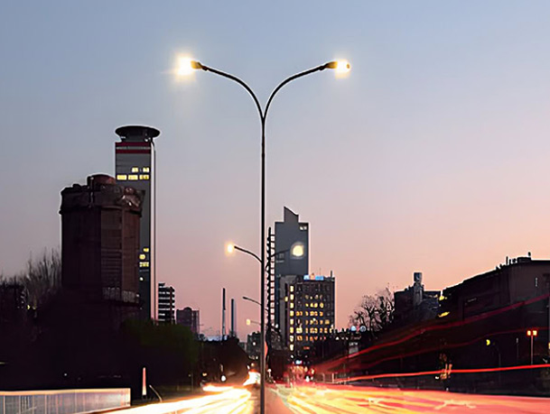
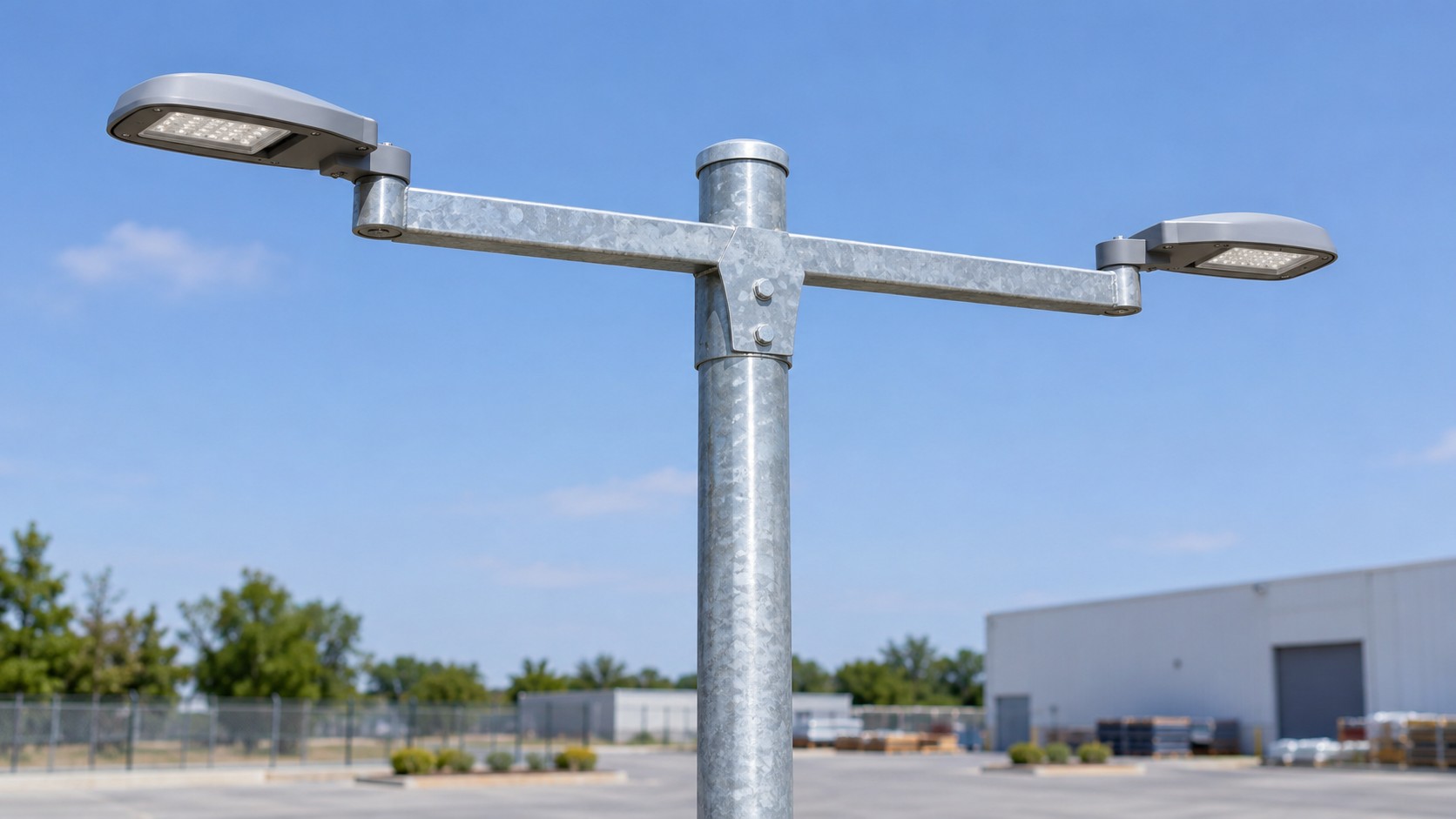
Two-light pole crossarm — application illustration.
A single outreach arm supports a luminaire at an offset from the pole. A lighting crossarm provides mounting positions along a shared member. “Double arm” commonly describes two arms on one pole, often pointing in opposed directions. These names describe hardware arrangements; the lighting layout depends on where each luminaire ends up and where it points.
Dynapole’s tubular and integral crossarm range (https://dynapole.com/products/tubular-and-integral-crossarms/) distinguishes pole-top and side-mounted configurations, with different fixture orientations. That is a useful reminder that selecting “a crossarm” leaves several layout decisions open.
Consider a hypothetical paved site requiring two luminaire mounting references at the same height. Set the pole centre as the origin; let x run across the site and y run along it. The required positions are L1 = (−1.2, 0) m and L2 = (+1.2, 0) m, both at an assumed mounting height of 8 m. The horizontal separation is 2.4 m.
Two opposed arms with mounting references 1.2 m from the pole centre could meet the positions above. A shared crossarm could also meet them if its mounting references occupy those coordinates. Its ordered overall length may differ from the 2.4 m fixture spacing because of end details and mounting hardware.
Rotate that same pair of references through 90°, and the separation remains 2.4 m. The positions become (0, −1.2) m and (0, +1.2) m. Both lights are now aligned along the site instead of across it. Neither the fixture count nor the separation has changed, yet the original position requirement is no longer met.
| Arrangement | L1 / L2 positions in plan, m | Result against the stated positions |
|---|---|---|
| Two individual opposed arms | (−1.2, 0) / (+1.2, 0) | Matches, if mounting height and aiming also agree |
| Crossarm across the site | (−1.2, 0) / (+1.2, 0) | Same position match; support design remains a separate check |
| Crossarm rotated 90° | (0, −1.2) / (0, +1.2) | Same spacing, different positions |
The lighting designer must still check the luminaire photometry, aiming and mounting geometry. Moving or rotating a support can change the light distribution on the site; the coordinate comparison establishes where the fixtures are, not whether illuminance, uniformity or glare criteria are met.
With two individual arms, each luminaire’s load enters its own arm before reaching the pole. With a shared crossarm, both fixture loads pass into that shared support and its pole connection. Arm self-weight, connection geometry and other attachments add to those loads.
Assume one 18 kg luminaire has its centre of gravity 1.2 m horizontally from an ideal arm-root reference. Using g = 9.81 m/s², its weight is 18 × 9.81 = 176.58 N. The gravitational moment about that reference is 176.58 × 1.2 = 211.90 N·m.
Two such luminaires contribute 353.16 N of downward force in total. The moment at each connection depends on its geometry. Opposed fixture positions do not eliminate bending within the arms.
This isolated dead-load calculation excludes support self-weight, wind, dynamic effects, load factors and connection design. It supplies no allowable load or member size. The 1.2 m is a centre-of-gravity offset for this calculation; it is not automatically the catalogue arm length or luminaire mounting-reference offset.
This explains why equal fixture counts and equal positions are only the starting point. The responsible designer needs the complete assembly and load basis. Hapco’s design guidance (https://www.hapco.com/design/design-and-applications/) identifies mounting height, equipment weight, effective projected area and wind conditions among the selection inputs. Those inputs must belong to the offered project configuration.
Where two directions need different outreach or mounting height, separate arms can make those differences explicit on the assembly drawing. Where the required points can be served along one member, a crossarm is a candidate. Pole-top versus side mounting, adjustment space and the luminaire’s fixing detail can decide whether a particular arrangement is practical.
Maintenance access also deserves a concrete comparison. Can a technician reach each fixture and its fixings using the planned equipment? Does the cable route allow the specified adjustment? Can the offered connections be assembled without interfering with another fixture or attachment? The arm and luminaire interface guide covers those connection details.
For opposed road lighting from a median, use the double-arm median guide alongside the road layout. A yard crossarm and a median double-arm pole may carry two lights while serving different geometries and maintenance constraints.
Return each proposal to the same L1/L2 positions, height and aiming requirements. Then compare the complete support, mounting parts, finish, cable provisions and installation scope. A cheaper bare bracket and a complete arm assembly are different supplies.
Jieyao Lighting’s single- and double-arm pole range provides product context for a road-pole enquiry. Discuss the layout and required assembly once the light positions and equipment have been defined.
Original layout examples and desk calculations. Revised 6 November 2026. The application image is generated.
Contact Us
Get a custom lighting solution and quotation for your project. Yangzhou Jieyao Lighting Equipment Co., Ltd. manufactures outdoor lighting and steel poles in Guoji Town Industrial Park, Gaoyou City, Yangzhou, Jiangsu, China. The company reports a 10,000 m² factory site, more than 60 employees including more than 10 technical personnel, and more than 100 production and testing machines. The present company name dates from 2017; Jieyao Poles’ published history traces the team’s manufacturing lineage to 2006. The stated 15 years of experience refers to the team. The company reports exports to more than 60 countries. Do you have any questions or requests?
Email: jay@jieyaolighting.com

Click to Chat.
Im online now.
 English
 Español
 Bahasa Indonesia