


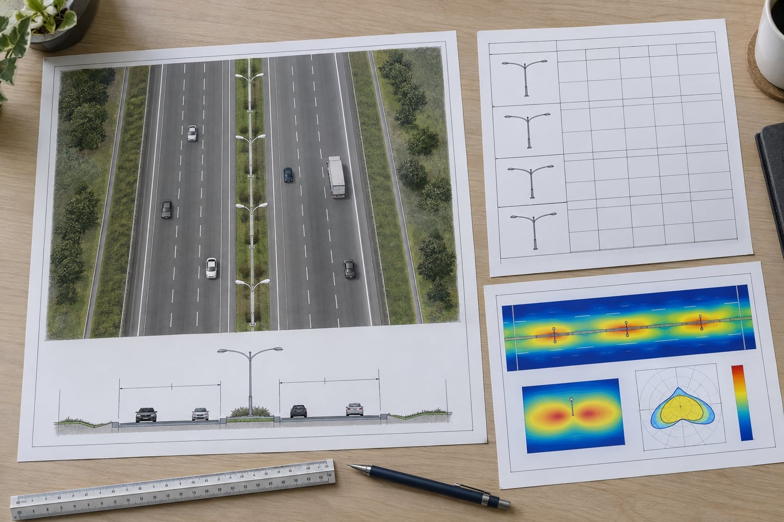
Coordinate the road cross-section, photometric layout, double-arm pole assembly, foundations, utilities, maintenance access and tender documents as one divided-road lighting system.
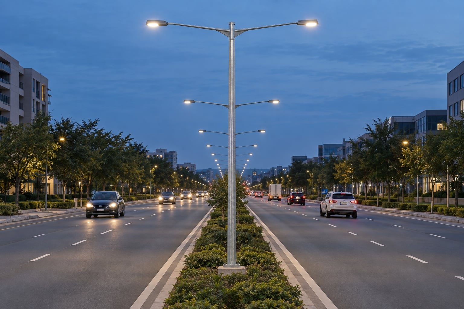
Divided urban road lighting often uses one line of double-arm poles in the central median to serve two carriageways. The arrangement can create a clear visual rhythm and reduce the number of pole rows, but it is not automatically suitable for every boulevard. Median width, lane count, verge activity, junction geometry, luminaire optics, wind exposure, underground services and maintenance access all influence the decision.
A useful design process begins with the road and its visual tasks. The photometric model establishes where light must be delivered. Structural and civil design then define how the complete pole assembly can be supported. Procurement documents should preserve these relationships so bidders compare the same scope instead of offering unrelated catalogue poles.
Record the width and direction of every lane, central median, shoulder, cycle track, parking bay, footway and verge. Add curb levels, drainage channels, barriers, trees, signs, bus stops and nearby building lines. These elements determine the useful pole positions and the surfaces that need calculation. A statement such as “six-lane road” does not explain whether the median is wide enough for a foundation or whether outer pedestrian areas need a second lighting layer.
Use a consistent chainage and pole-mark system across the lighting, civil, electrical and landscape drawings. Mark regular sections separately from junction approaches, turn pockets and transitions. When the cross-section changes, the lighting arrangement may also need to change rather than forcing one spacing and bracket onto the whole route.
| Road zone | Evidence to map | Lighting and pole decision |
|---|---|---|
| Regular divided section | Lane and median widths, setbacks, speed, road surface and adjacent uses | Candidate median or verge layout, optics, height, spacing and control group |
| Junction and turn pocket | Widening, stop lines, signals, signs, channelization and sight triangles | Local pole shifts, supplementary positions and glare check without blocking visibility |
| Crossing or transit stop | Pedestrian route, refuge, shelter, queue area, trees and vertical surfaces | Vertical visibility, conflict-zone coverage and coordinated pedestrian lighting |
| Bridge or constrained median | Structural deck, barriers, expansion joints, utilities and access restrictions | Project-specific support, alternative pole line or transition arrangement |
| End of median | Merge geometry, approach direction, island nose, signs and maintenance position | Safe terminal pole location and a deliberate transition to verge or intersection lighting |
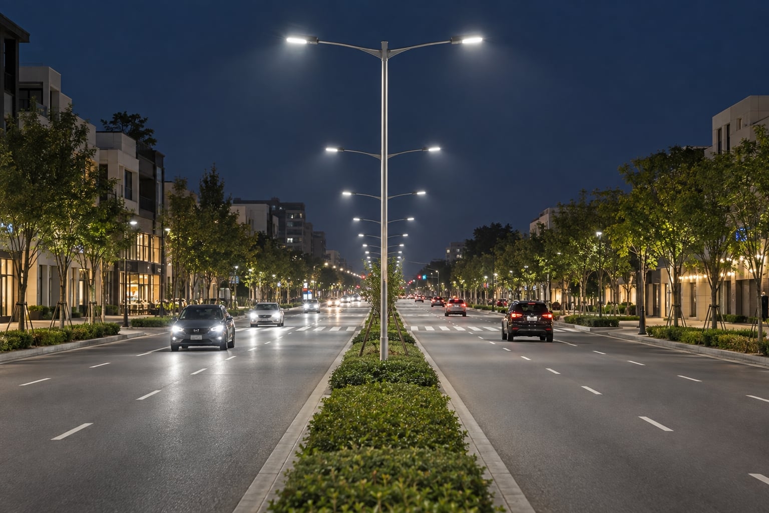
A median pole line can illuminate both directions from one structural position. It may keep poles away from shopfronts, driveways and outer sidewalks. However, the foundation competes with landscaping, drainage and utilities, while maintenance may require traffic control in the innermost lane. A narrow median may not provide enough physical space or recovery distance for the preferred assembly.
Verge poles can give easier access from the road edge and may support footway lighting, but two rows may be required. They can also conflict with trees, entrances, overhead lines and pedestrian activity. Compare complete layouts through photometry, civil feasibility, electrical routing and maintenance planning. Do not select the median arrangement solely because it appears to use fewer poles.
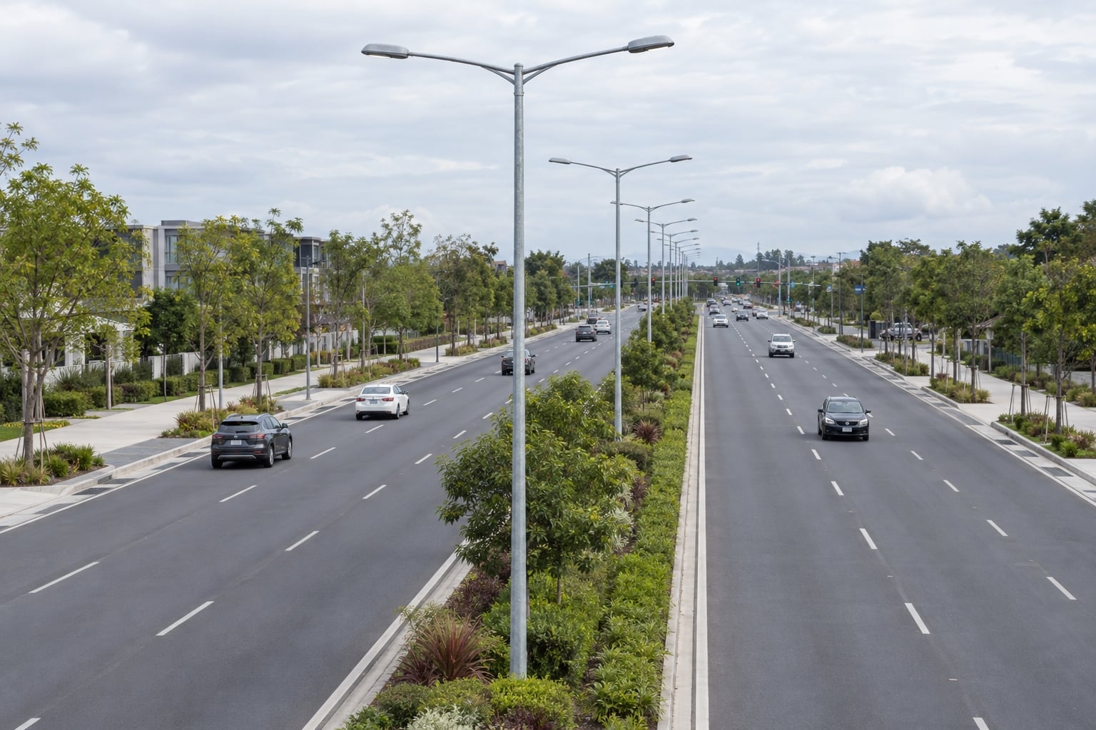
The photometric design establishes candidate pole positions, mounting height, arm reach, luminaire tilt and optical distribution. Model both carriageways and relevant adjacent surfaces using the maintained criteria required by the project. Include lane edges, junctions, crossings, refuge islands and any footways that the road-lighting system is expected to serve.
Use tested luminaire data and state the maintenance factors, surface assumptions and calculation grids. A wattage comparison cannot demonstrate uniformity, glare control or useful light placement. Once a workable layout is identified, freeze the actual luminaire dimensions, mass and projected area so the structural review uses the same equipment that produced the lighting result.
Mounting height affects coverage, glare, pole count, wind demand and maintenance equipment. Spacing depends on the road width, optical distribution, required uniformity, median position, setbacks and local changes in geometry. A fixed spacing-to-height ratio may help with early options, but it does not replace calculation for the issued design.
Test more than one arrangement where the project allows it. A taller pole with wider spacing may reduce foundations but increase top load and access height. A lower, closer layout can follow junction changes more precisely but adds foundations, cable joints and equipment locations. Compare the complete route instead of optimizing only the regular mid-block section.
Opposite carriageways can have different lane counts, turn pockets, bus lanes, parking edges or surface conditions. Buildings and trees may also create different boundary constraints. A visually symmetric double-arm pole does not require identical optics on both sides if the photometric tasks differ, but the equipment schedule must record each luminaire accurately.
Where one side is wider, the arm reach or luminaire distribution may change. Keep the resulting eccentricity and projected area in the structural input. If two different luminaires or aiming settings share one pole, give them distinct identifiers so installation and maintenance teams do not reverse the left and right equipment.
The bracket places each luminaire relative to the lane. Define outreach, rise, tilt, spigot diameter, insertion depth and rotation control from the approved layout and luminaire interface. Long arms can shift the light distribution without moving the foundation, but they also increase moment, vibration sensitivity and transportation complexity.
A 10m double-arm street light pole is a useful product family for many divided roads, yet the final assembly remains project-specific. The drawing should show the shaft-to-head connection, arm orientation and both fixture interfaces. Avoid describing the bracket only as “double arm,” because many geometries can share that name.
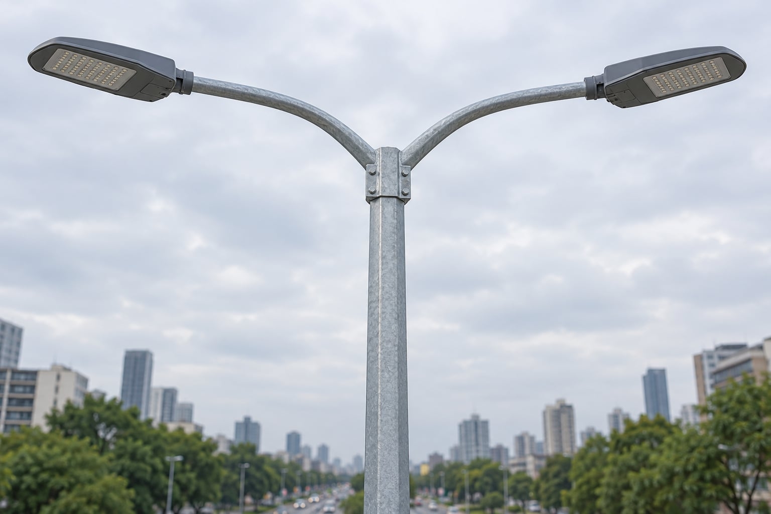
The structural basis includes the governing standard, site wind speed, terrain or exposure, topography, risk category and required load combinations. The equipment schedule should provide the quantity, mass, dimensions, mounting level and effective projected area of every luminaire, arm, sign, camera or permitted future attachment.
Two luminaires and two arms create different wind and torsional demand from a single roadside fixture. Do not compare poles by nominal height or wall thickness alone. Request calculations and evidence appropriate to the contract, and keep the approved load schedule linked to each pole mark. The wind load and EPA procurement checklist explains the input discipline even though high-mast structures use a different system.
A graphic pole symbol can fit where the actual foundation cannot. Confirm the available median width below the curb, not only the landscaped surface width. Account for barrier footings, drainage structures, ducts, irrigation, tree root zones and the required separation from live lanes. The foundation designer also needs structural reactions, soil information, groundwater or frost conditions and local design requirements.
Coordinate the base plate, anchor pattern, conduit opening and finished level before civil release. The pole supplier can provide connection dimensions and reactions, while the responsible civil or structural designer determines the site foundation. Use the street light pole foundation and anchor bolt guide to organize this interface.
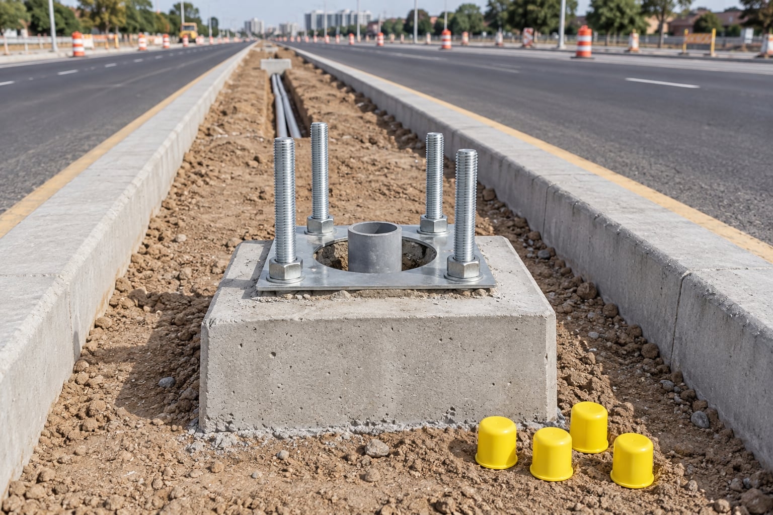
Medians often collect more infrastructure than a lighting drawing reveals. Stormwater inlets, subsoil drains, irrigation lines, signal ducts, communications, power cables and future utility sleeves may occupy the same corridor. Combine these systems on a coordinated plan and section before foundations are set out.
Set the pedestal so water does not pond around the base or enter the access opening. Maintain drain paths through landscaped areas and avoid directing irrigation spray into doors or cable entries. Where the route crosses a junction controller or signal duct bank, agree clear vertical and horizontal separation rather than shifting the pole informally on site.
The access opening should face a location where technicians can work with controlled exposure to traffic. On a narrow median, either orientation may place the door near a live lane, so the maintenance method and traffic management plan must be considered. The door direction should be shown by pole mark rather than left to the erection crew.
Provide enough internal space for the specified terminal arrangement, protective devices, cable bends and earthing connection. Keep the opening clear of soil, mulch and irrigation. If barriers or dense planting surround the pole, verify that the door can still open and that test equipment can be used without unsafe body position.
At major intersections, the median may widen, taper, stop or split around turn lanes. Signal poles, signs and controller equipment add visual and physical constraints. Recalculate these zones instead of continuing the regular pole spacing through them. Pole locations should preserve sight triangles and remain clear of swept paths and crash-sensitive island noses.
The lighting designer should coordinate stop lines, crossings, channelized islands and approach geometry with the traffic plan. Supplementary verge or corner poles may be more suitable than forcing a double-arm median pole into a constrained location. Document the transition so the contractor does not assume that every pole along the project is the same family.
Pedestrians and cyclists need more than average horizontal road illumination. Map crossings, refuges, bus shelters, cycle-lane conflicts and routes between stops and adjacent buildings. Review vertical visibility and glare from the user viewpoint. A central pole line may contribute useful light but may not adequately cover every outer sidewalk or shelter.
Coordinate pedestrian-scale fixtures, shelter lighting or building-mounted equipment where required. Avoid placing poles, cabinets or foundation projections within accessible routes. At refuge islands, keep luminaires and signal equipment organized so they do not create confusing silhouettes or obstruct people waiting between traffic streams.
Median landscaping can improve the street environment, but mature canopy can block light and maintenance access. Coordinate tree species, expected crown size, trunk position and root volume with the pole schedule. A young planting plan should be tested against the mature condition rather than photographed only at handover.
Keep roots away from foundations and ducts where practical, and preserve room for safe pruning. Repeatedly cutting trees to clear luminaires is not a stable design strategy. If a continuous canopy is important, compare verge lighting, offset pole positions or different optics through calculation before construction begins.
Divide circuits by route, junction priority, control strategy and maintenance isolation. A fault or planned repair should not create a long dark section across both carriageways. Coordinate cable routes, voltage drop, protective devices, earthing and surge protection with the electrical design and the actual pole compartment.
Where luminaires on opposite arms require separate control or monitoring, record the wiring arrangement clearly. Keep pole identifiers, circuit numbers, controller addresses and luminaire marks consistent across schedules. This helps commissioning teams test both sides and prevents maintenance crews from replacing the wrong driver or optical unit.
Time schedules, central management or traffic-responsive dimming can reduce energy use during low activity. The control plan should state normal and reduced scenes, transition times, overrides, failure behavior and zones that remain at a higher level. Junctions, crossings and complex approaches may need different treatment from regular mid-block sections.
Commission the reduced scene as well as full output. Review both carriageways, side roads and pedestrian areas after the system stabilizes. A control strategy should preserve visual continuity; a sudden step from a bright commercial segment to a dark median section can reduce recognition even when each calculation point appears acceptable in isolation.
Double-arm median poles direct light outward toward both sides, so optical control matters near homes, shops, upper windows and drivers approaching on curves. Review glare and backlight using the actual aiming, mounting height and road profile. Excess output cannot compensate for an unsuitable distribution.
If shields or revised tilt are needed, include them in the photometric file and equipment schedule. Field adjustments should be recorded because small changes can affect both uniformity and glare. Keep architectural or pedestrian lighting coordinated so overlapping systems do not produce unwanted brightness at the road boundary.
Median poles can require a lane closure or specialized access vehicle for luminaire work. Identify the safe working lane, traffic-control space, lift reach, overhead clearances and times when maintenance is permitted. A landscaped median may prevent vehicle placement even when the pole itself is accessible from the curb.
Standardize serviceable components where practical and make doors, drivers and terminal arrangements accessible with normal tools. Record arm orientation and luminaire mark so replacements preserve the approved configuration. If safe access is not achievable, revisit the pole line or mounting arrangement before tender rather than transferring the problem to operations.
Replacing older luminaires changes photometry, mass, projected area, surge components and sometimes arm loading. Survey the existing shafts, brackets, doors, bases, anchors, corrosion condition and foundation context. Confirm whether original drawings and structural calculations are available; visual appearance alone cannot prove capacity.
Model the proposed luminaire on the actual road geometry and review dark transitions, glare and changed land use. Where the existing pole line cannot meet the required arrangement, compare targeted replacement, additional positions or a revised bracket rather than installing one retrofit kit throughout the route without verification.
Hot-dip galvanizing is a common baseline for steel roadway poles, but the project should define the applicable standard, inspection criteria and repair method. Coastal salt, de-icing chemicals, industrial emissions, persistent irrigation and standing water can increase exposure. A compatible additional coating may be considered where the environment and maintenance plan justify it.
Coordinate vent and drain details with fabrication and galvanizing. Protect surfaces during transport and erection, especially around base plates, doors and bracket connections. Color requirements should not obscure the need for a complete coating system and defined touch-up procedure.
State whether the pole supplier provides the shaft, double-arm head, spigots, base plate, anchor assembly, access door, internal terminal support, finish, packing, drawings and calculations. Identify items by others, including luminaires, foundations, cabling, controls, erection and testing. Scope boundaries should be visible in the schedule rather than buried in general notes.
Where a route changes to roadside poles, taller highway poles or another family, give each type a separate mark. The 10m single-arm street light pole can support verge sections, while a 12m highway lighting pole addresses a different height and load range. Do not merge these into one ambiguous description.
The approval package should connect pole marks, quantities, dimensions, bracket orientation, luminaire data, design loads, base interface, openings, finish and packing sections. Required calculations, material records, coating inspection, weld inspection or other evidence should follow the contract and applicable standards. A list of certificates cannot replace project-specific geometry and load information.
Use a document register with revision and status. Confirm which drawings are for review, approval, fabrication or as-built record. The street light pole shop drawing checklist provides a structured post-award review sequence.
| RFQ package | Buyer provides | Bidder returns | Release check |
|---|---|---|---|
| Road and lighting basis | Plans, sections, pole marks, lighting criteria and luminaire schedule | Confirmed quantities, interfaces, exclusions and deviations | All marks map to one issued layout |
| Structural basis | Wind inputs, equipment mass, EPA, mounting levels and standard | Pole geometry, materials, design assumptions and required calculations | Returned design uses the scheduled top load |
| Civil and electrical interfaces | Foundation responsibility, levels, ducts, earthing and access direction | Base, anchors, conduit opening, door and terminal arrangement | Interfaces fit the coordinated median section |
| Finish and evidence | Exposure, coating requirement, inspection plan and document list | Proposed process, inspection records, repair method and submittal index | Evidence matches the specified acceptance route |
| Delivery and handover | Phases, transport limits, packing marks and site sequence | Packing proposal, delivery schedule and final record package | Long components and accessories remain traceable |
Normalize every proposal against the same pole schedule, luminaire loads, wind basis, interface responsibilities, finish and document scope. Separate compliant offers, declared alternatives and missing information. A heavier pole or longer material list is not automatically a better engineered solution, and a low total mass does not prove noncompliance.
Record clarifications and accepted deviations before award. Confirm whether anchors, brackets, calculations, inspection records and packing are included. The decision should remain traceable to the project requirements instead of relying on a supplier ranking or a single catalogue value.
Before erection, verify foundation level, anchor projection, bolt pattern, conduit position and pole mark. Inspect shafts and arms for transport damage and confirm that the correct head assembly is paired with each shaft. Use the approved lifting method and do not force a base plate into alignment by excessive bolt load.
After erection, check verticality, arm orientation, fasteners, access doors, earthing, cable termination and luminaire aiming. Complete night commissioning under representative road conditions. Measure and observe the agreed criteria, review glare and transitions, and record any approved aiming changes or control settings.
The final record should include as-built pole coordinates, pole and luminaire schedules, approved drawings, foundation interfaces, circuit information, control settings, inspection results and maintenance data. Link every installed pole mark to the correct arm, luminaire and electrical group. This protects the design when parts are replaced or the road is widened.
Retain the final night-test record and the revision that reflects field adjustments. If landscaping, transit or junction works are completed later, update the lighting record where those changes affect visibility or access. A reliable asset register gives future teams a sound basis for maintenance and retrofit decisions.
No. Compare median space, photometry, foundations, utilities and maintenance with verge alternatives.
Yes, when the photometric and structural schedules identify both units and their orientation clearly.
Road width, pole position, luminaire optics, aiming, mounting height and structural limits.
Not automatically, but the real foundation, clearance and maintenance space must be verified.
Through photometric calculation using the actual road, luminaire, height and project criteria.
Quantity, dimensions, mass, EPA, mounting level and position for every attachment.
The responsible project designer uses pole reactions, soil data and local requirements.
It keeps maintenance work on the safer side and prevents conflicts with planting or barriers.
Sometimes, but outer pedestrian areas must be calculated and may need separate fixtures.
Approved layout, load schedule, wind basis, interfaces, finish, documents and delivery scope.
Send the road plan and cross-section, pole schedule, luminaire data, wind basis, median constraints, finish requirement and document list. Jieyao can review the galvanized pole, double-arm assembly and manufacturing interfaces against those project inputs.
Discuss Your Median Pole Requirements
Street Light Pole Height Guide: How to Select Moun
Integrated and Split Solar Street Lights Compariso
How to Choose the Right Solar Street Light Pole
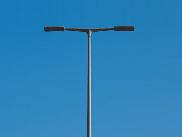
Street Light Pole Cost Factors and Quotation Compa
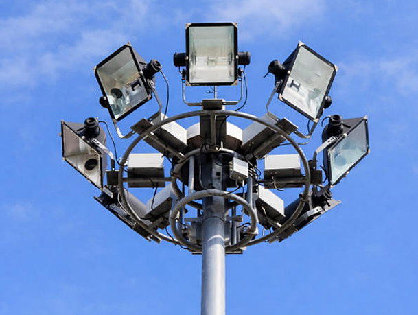
High Mast Light Specifications and Selection Guide
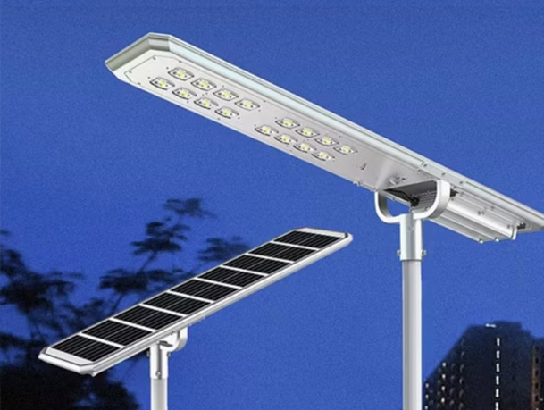
Features of All in One Solar Street Lights
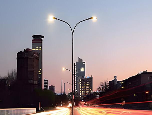
How to Choose the Right LED Street Lights for Your
Select the Right LED Stadium Light for Football Pi
6-meter steel lamp post, 150W solar landscape ligh
Solar Street Lights Installed at Baybay Black Sand
Contact Us
Get a custom lighting solution and quotation for your project. Outdoor lighting manufacturer in Yangzhou, ChinaAbout Jieyao LightingYangzhou Jieyao Lighting Equipment Co., Ltd. is an outdoor lighting manufacturer focused on solar street light systems and high mas... Do you have any questions or requests?
Email: jay@jieyaolighting.com

Click to Chat.
Im online now.
Hey, I'm Xu Jie from Jieyao Lighting. What can I do for you? Welcome to contact me, WhatsApp: +86 13815843784
WhatsApp Us
🟢 Online | Privacy policy