
A high mast lighting control panel coordinates the power circuits, switching and operating controls specified for the mast system. Lighting control, LED drivers and the lowering mechanism perform different jobs. They may be housed together or separately, so identify each function before comparing cabinet photographs or equipment lists.
What this guide covers
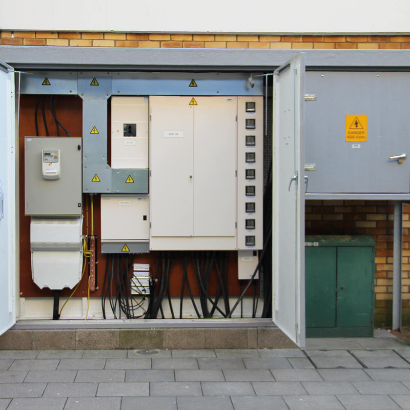
An outdoor lighting cabinet — an installation example.
Begin with a one-line diagram showing where the supply enters and which outgoing circuits it feeds. Then identify how those circuits are switched and what tells them to operate. This is easier to follow than treating every item in a cabinet as a “controller”.
The enclosure provides the physical housing. Protective and isolating devices belong to the electrical design. Contactors or relays switch the specified loads. A timer, photocell input or network controller provides commands. Terminals and circuit labels connect the equipment to the drawing. Each function needs to be visible in the proposed scope.

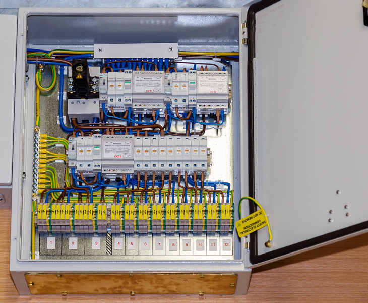
Numbered circuits and terminal identification in a lighting panel.
The numbered panel photograph shows why circuit identification is useful. A maintenance team needs to connect a drawing reference to a physical circuit. The photograph does not establish a current rating, protection coordination, enclosure rating or suitability for a particular site.
On a phone, swipe this table sideways to see the final column.
| Function | What it does | What to request |
|---|---|---|
| Supply and protection | Feeds and protects the defined outgoing circuits | One-line diagram, supply basis and selected device schedule |
| Switching | Opens or closes lighting circuits on command | Contactor/relay arrangement and compatibility with the actual LED loads |
| Scheduling or sensing | Decides when lighting should operate | Control description, time basis, sensor location and override behaviour |
| LED driving or dimming | Operates or varies the selected luminaire output | Driver location, model and compatible control interface |
| Lowering control | Operates the selected service mechanism | Separate operating documents, isolation and control interfaces |
| Identification and access | Makes the installed assembly understandable and serviceable | Circuit labels, terminal references, drawings and access arrangement |
A contactor-controlled circuit generally answers whether a group is energised. A dimming interface determines the permitted output command for a compatible driver. If a project needs reduced output during quiet hours, ask how that command reaches each driver, rather than assuming a time switch alone provides dimming.
The same distinction applies to monitoring. A panel that can switch a circuit is not automatically reporting each fixture’s condition or energy use. List the required signals and feedback explicitly when remote operation is part of the project.
A dusk-based command follows an agreed light-sensing arrangement; a time schedule follows a clock or astronomical calculation. Remote commands can be added where the selected system supports them. The useful procurement question is how the functions interact: what happens at dusk, at a scheduled dimming event, during a manual override and after supply restoration?
Use a simple sequence-of-operation description with the circuit schedule. For example, a site may request ordinary lighting on a dusk command and a separate scheduled reduction command to compatible drivers. That is a hypothetical operating requirement, not a wiring diagram or a claim about the cabinets pictured here.
The detailed choice between sensing and scheduling is covered in the photocell and astronomical time-switch guide. This page concerns how those commands fit within the complete mast-panel scope.
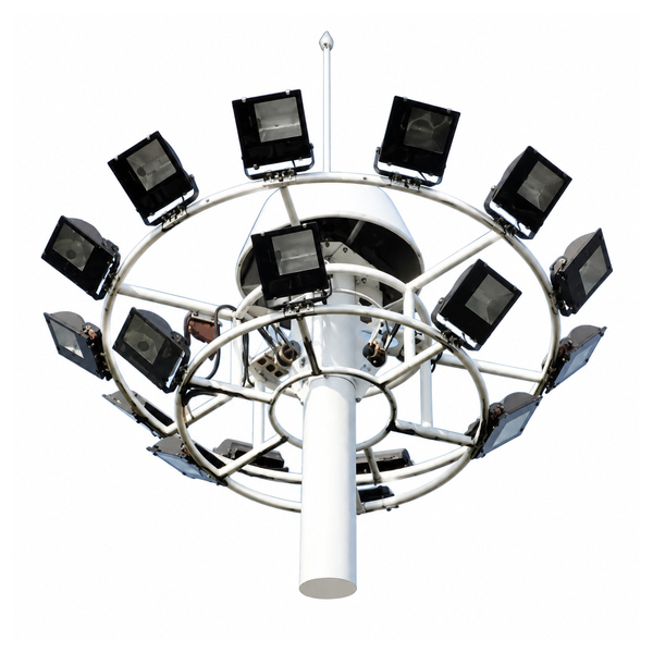
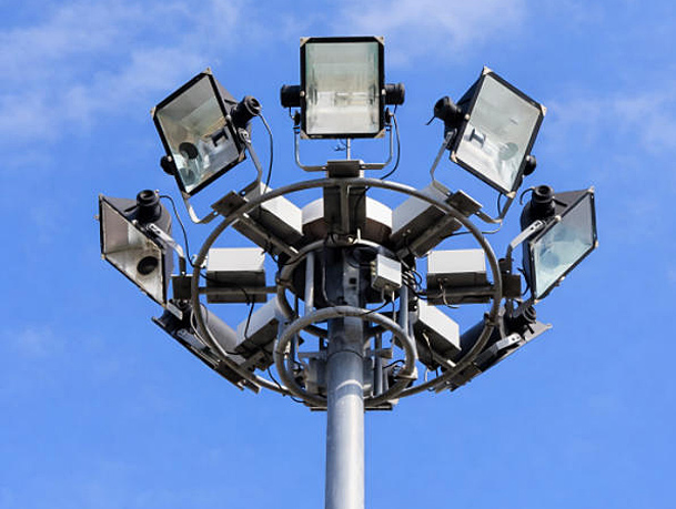
A high mast lighting carriage — its service mechanism has separate control requirements.
The lowering drive moves equipment for maintenance; the lighting circuits power the luminaires. They need coordinated but distinct isolation, connection and operating arrangements. Some systems use a portable drive and control unit, while others use an installed drive. Match the controls to the actual mechanism and its operating manual.
A generic lighting cabinet should not be treated as a replacement for the lowering system’s controls. The high-mast winch guide covers the mechanism selection questions. Qualified personnel should use the selected system’s operating documents and the site electrical design.
One mast does not necessarily mean one switched circuit. The circuit schedule describes which luminaires operate together and how those groups relate to the site task. For example, a project may request separate operating groups for a working area and a circulation route. That is a proposed requirement to develop with the lighting and electrical design, not a claim about the numbered cabinet pictured here.
Grouping also affects fault investigation and maintenance planning. Clear circuit labels help staff relate an outgoing circuit to the drawing, but a circuit number alone does not describe the complete isolation arrangement. Supply a schedule that identifies the equipment served, its circuit reference and the relevant control function.
Describe when the lights should start, which group should reduce output and when full output should return. The designer can then identify the switching and compatible dimming interfaces. A single “timer included” line leaves unanswered whether it only switches the supply or sends a separate output command to the drivers.
State how authorised staff need to test the lighting and how normal automatic operation is restored. A manual command and an electrical isolation function are different requirements. Their controls, indication and documentation should make that distinction understandable at handover.
List the information the operator actually needs: a command acknowledgement, circuit status, equipment alarms or measured energy, for example. Those are different signals. A communication connection does not by itself establish that each is available, and a group-level signal should not be presented as individual-fixture monitoring.
Some lighting arrangements place drivers at the luminaires; other selected systems use a remote arrangement. Identify the actual proposed driver location and its matching luminaire configuration. A cabinet photograph showing spare physical space is insufficient to approve remote drivers, cable lengths or a revised electrical layout.
Driver location changes the information needed from the equipment supplier and the routes shown on the drawings. Compare the complete luminaire-and-driver system, including its connection and service documents. Do not move a driver into a convenient enclosure solely because a different mast installation appears to use that arrangement.
Agree the expected result for each permitted command and record the observed result at commissioning. The plan can cover automatic start, scheduled changes, manual operation, restoration of the normal mode and the feedback specified for the system. The selected equipment manuals and electrical design govern how qualified personnel conduct those checks.
Keep the resulting settings and circuit references with the as-built drawings. This gives the maintenance team a known operating description to compare against when a circuit later behaves differently, rather than leaving it to infer the intended sequence from the devices inside the door.
Send the mast and luminaire schedule, actual driver/load data, available supply, required circuit grouping and operating behaviour. State whether drivers, communications, the lowering drive and site cabling are included or separate. The required enclosure performance must match the environment and the complete assembled cabinet, not merely a component label.
At handover, ask for the as-built circuit schedule, terminal identification, selected-device documentation, control settings and agreed test records. These make a panel understandable after installation and help prevent one supplier’s cabinet from being compared with another’s bare enclosure.
Jieyao Lighting can coordinate the required steel-mast and equipment scope through a project enquiry. For estimating load current, use the separate lighting-system current guide with the actual electrical inputs.
Schneider Electric, Standalone Lighting Control Relay Panels — Indoor commercial relay-panel example separating switching, scheduling and controller functions.
https://www.se.com/ca/en/product-range/61308-relay-panel-standalone/
Schneider Electric, IC twilight switches — Manufacturer information about light-sensing switching controls.
https://www.se.com/hk/en/product-range/843-ic/
Holophane, LDV high-mast lowering devices — Model-specific lowering equipment and manuals demonstrate why the operating controls must match the chosen mechanism.
https://www.acuitybrands.com/products/detail/1312479/holophane/ldv-device/high-mast-lowering-devices
Contact Us
Get a custom lighting solution and quotation for your project. Yangzhou Jieyao Lighting Equipment Co., Ltd. manufactures outdoor lighting and steel poles in Guoji Town Industrial Park, Gaoyou City, Yangzhou, Jiangsu, China. The company reports a 10,000 m² factory site, more than 60 employees including more than 10 technical personnel, and more than 100 production and testing machines. The present company name dates from 2017; Jieyao Poles’ published history traces the team’s manufacturing lineage to 2006. The stated 15 years of experience refers to the team. The company reports exports to more than 60 countries. Do you have any questions or requests?
Email: jay@jieyaolighting.com

Click to Chat.
Im online now.
 English
 Español
 Bahasa Indonesia