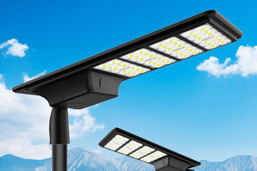

Floodlight mounting options usually start with a yoke or trunnion bracket, a slipfitter on a tenon, or a model-specific arm or plate. A crossarm or headframe then positions one or more of these fixtures on the pole. Choose the fixture connection and the supporting frame together, keeping the required aiming movement available.
What this guide covers

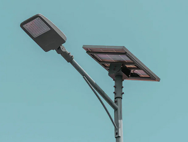
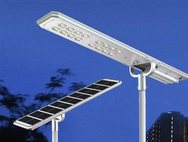
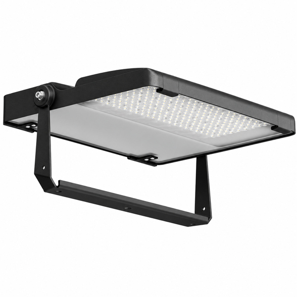
A floodlight in a yoke-style bracket — product mounting example.
Follow the load path in a photograph: floodlight housing → fixing bracket → arm or frame → shaft. These are separate interfaces. A yoke can bolt to a crossarm, and a slipfitter can fit onto a tenon projecting from a headframe. Naming only the pole-top shape leaves the fixture connection unresolved.
A yoke-style bracket wraps around part of the floodlight and connects through side pivots. The terms “yoke” and “trunnion” are used in manufacturer literature for related mounting arrangements; the actual drawing is more useful than assuming all suppliers use the terms identically.
The bracket can provide a flat mounting surface while allowing the fixture to tilt. This is useful on frames, platforms and wall-mounted supports when the fixing pattern and aiming range are compatible. Check that the body, heat sink, cable and nearby fixtures remain clear throughout the intended movement.
A bracket that appears to rotate freely in a catalogue image may have a limited permitted operating orientation. Use the selected model’s instructions to establish the allowable tilt and fastening procedure. Do not transfer a torque value or aiming limit from a different floodlight.
A slipfitter is a socket-style connection that fits over an appropriately designed projecting tube or tenon. The tenon is the supporting projection, not the name of the complete floodlight mount. Mating dimensions, insertion, cable path and the specified retention details determine compatibility.
A nominal pipe label is not an outside-diameter measurement. For example, Cooper’s TRU instructions describe a mount for a 2-inch nominal pipe with a 2⅜-inch outside diameter. That outside diameter is about 60.3 mm. It is a model-specific example of why a buyer should exchange actual mating dimensions, not a universal tenon size.
Also record whether the tenon is vertical, horizontal or angled. A mount intended for one orientation may not provide the required movement or weather detailing in another. Changing an adapter can move the fixture’s centre of gravity and its position in the lighting layout.
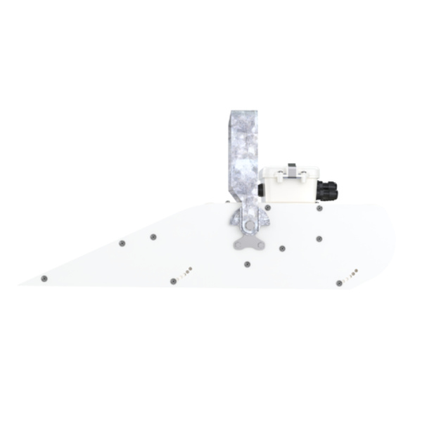
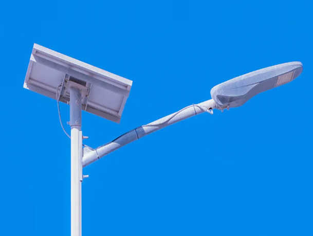
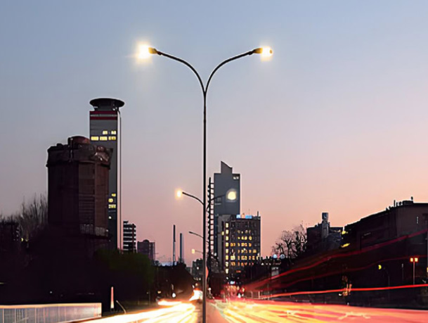
Floodlight side bracket and pivot fixing — a mounting detail.
Some fixtures use a dedicated arm or plate instead of a generic pipe socket. The fixing holes, access to fasteners and cable opening should be checked together. Replacing a fitting with one that shares only the same bolt spacing can still create a cable or aiming clash.
For an existing pole, identify which parts will stay and which will be supplied with the new fixture. A proposed adapter should appear on the assembly drawing with its material, connection and equipment loads reviewed. It should not emerge as an improvised site solution after delivery.
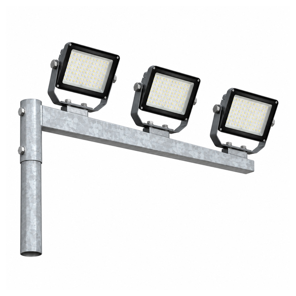
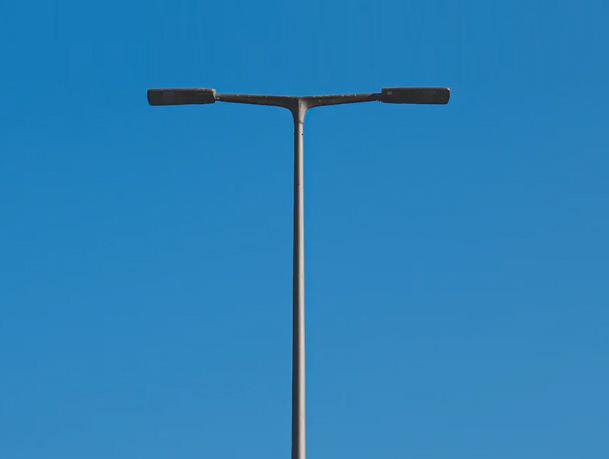
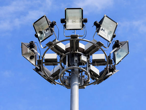
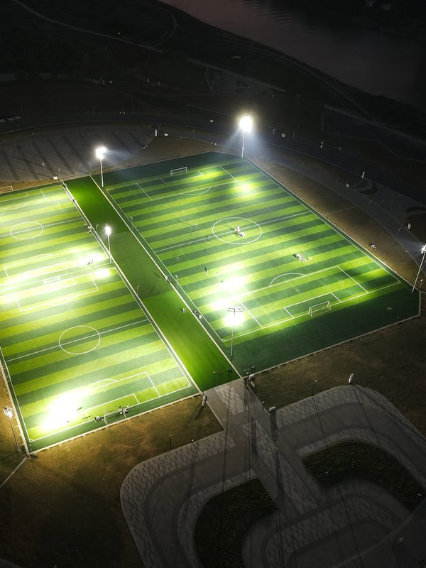
A directional crossarm carrying several floodlights.
A crossarm sets the positions of several fixtures; each fixture still needs its own compatible mount. A circular, rectangular or directional head can carry different mounting interfaces. Head shape alone does not establish beam direction, lamp count or whether the assembly lowers.
On a phone, swipe this table sideways to see the final column.
| Connection | Look for | Check before selection |
|---|---|---|
| Yoke / trunnion | Bracket with side pivots and a mounting face | Hole pattern, permitted orientation, aiming clearance and cable movement |
| Slipfitter / tenon | Socket fitting over a projecting support | Actual outside/inside dimensions, engagement and retention details |
| Dedicated arm / plate | Model-specific bolted interface | Matching drawing, cable opening, gasket/contact surfaces and access |
| Crossarm / headframe | Structure positioning multiple fixtures | Fixture spacing, individual mounts, combined loading and maintenance access |
A yoke can provide a mounting face and an adjustable fixture position where the selected model permits it. Draw the supporting surface and the fixture together, including the space behind the housing. Access to a fixing bolt can disappear when the lamp is aimed, and the supply cable needs a route that remains clear of the moving bracket.
Begin with the intended target for each light, then place the fixtures on the crossarm. Several identical brackets may need different aiming positions. Compare the movement envelopes so one housing does not obstruct another, and check that each final position can be reached and secured. A longer crossarm changes the supporting structure as well as the available spacing.
The fixture mount must suit the head’s maintenance arrangement. If the carriage lowers, consider the positions of the fixtures, cables and brackets through the specified travel as well as in the operating position. A fixture that fits the head while standing still can still conflict with another part during servicing. Use the complete mast-system drawing for this check.
Record the retained interface before selecting the new fixture: the tenon’s actual dimensions and orientation, or the plate’s hole pattern and available contact surface. Identify the old fixture separately from the pole support. The bracket supplied with a replacement luminaire may be entirely different even when the two housings have a similar shape.
Then compare the new housing envelope, cable-entry position and intended aiming with the existing installation. An adapter can bridge an interface, but it also becomes another designed connection. Include it in the drawing and equipment load schedule. This avoids treating an extra plate or sleeve as a harmless accessory after the pole has already been checked.
The mating connection: show the actual tenon or mounting surface and the fixture-side interface. The working position: show the light’s orientation and the clearance needed to reach it. The cable route: show where the cable enters and moves relative to the bracket. The service access: show how installers and maintainers reach the relevant fixing points.
Together these details explain more than a product photograph alone. The yoke photograph shows a pivoting bracket; the side-view photograph shows the bracket and pivot fixing; the crossarm photograph shows how several fixtures are positioned. None of those images supplies the missing mating dimensions for a different model.
Put both proposed fixture drawings beside the same pole-head drawing. Mark the final light positions and aiming directions. Ask whether every fastener can be reached after assembly and whether the cable route remains protected. Then compare the complete mass and wind-area inputs with the pole design.
This short comparison is more useful than selecting a mount because it looks stronger. The correct assembly is the one that fits the approved fixture, supports its loads and allows the intended lighting position.
See the arm and luminaire interface guide for detailed release checks, and high mast type guide for headframe and maintenance categories. Send Jieyao Lighting the fixture and head drawings when requesting a coordinated mounting proposal.
Cooper Lighting Solutions, TRU Tribute instructions, mounting section — TRU model instructions, including the nominal-pipe and actual outside-diameter example.
https://www.cooperlighting.com/api/assets/v1/file/CLS/content/561562535c5e48869dfaad40006e3104/Streetworks-Installation-Instruction-Sheet-for-TRU-Tribute.pdf
Cooper Lighting Solutions, XAS Area Site instructions — XAS model instructions covering pole-arm, slipfitter and yoke arrangements.
https://www.cooperlighting.com/api/assets/v1/file/CLS/content/IB51588326EN-lumarkap-xas-ins/Lumark-AP-XAS-Installation-Instructions.pdf
Contact Us
Get a custom lighting solution and quotation for your project. Yangzhou Jieyao Lighting Equipment Co., Ltd. manufactures outdoor lighting and steel poles in Guoji Town Industrial Park, Gaoyou City, Yangzhou, Jiangsu, China. The company reports a 10,000 m² factory site, more than 60 employees including more than 10 technical personnel, and more than 100 production and testing machines. The present company name dates from 2017; Jieyao Poles’ published history traces the team’s manufacturing lineage to 2006. The stated 15 years of experience refers to the team. The company reports exports to more than 60 countries. Do you have any questions or requests?
Email: jay@jieyaolighting.com

Click to Chat.
Im online now.
 English
 Español
 Bahasa Indonesia