
Container terminal lighting needs to be checked with containers in place. Define the stacking envelope, traffic lanes and working surfaces, then compare mast positions and optics across representative yard states. An empty-yard average lux calculation can miss a blocked light path in an occupied lane.
A storage block changes as boxes arrive, leave and move between rows. This guide focuses on that changing geometry: how a stack interrupts direct light, which task planes belong in the model, and what evidence a buyer should request. For berth boundaries and water-facing navigation views, use the separate port and quay lighting guide.
In this guide: Stack model · Shadow calculation · Task planes · Verification · Download worksheet

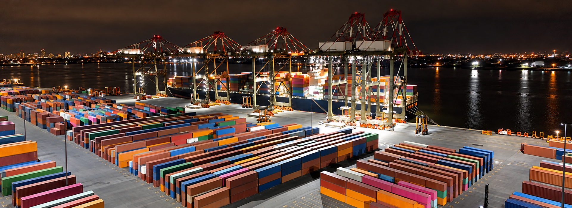
Container stacks and handling areas at a port terminal — an application example.
Start with a yard plan showing stack-block boundaries, maximum operating heights, aisles, reefer areas, pedestrian routes and handling-equipment envelopes. Add mast coordinates and access areas. Separate the normal operating stack from an exceptional permitted stack; the owner should identify which states the lighting design must support.
An empty yard remains useful as a reference, but it cannot stand in for the occupied terminal. Compare the same luminaires, maintenance assumptions and control scene while changing the obstruction state. This isolates the layout question before fixture quantity or input power is changed.
↔ Swipe to read all columns.
| Operating state | What changes in the model | What to review |
|---|---|---|
| Empty reference | No container obstruction; retain fixed structures | Baseline coverage and boundaries |
| Representative occupied block | Actual row envelope and working aisles | Dark strips beside stacks and driver transitions |
| Maximum permitted stacking | Owner-defined height and edge positions | Access routes and tasks hidden from a mast |
| Active handling / revised block | Crane or vehicle envelope and changed row position | Temporary obstruction, cab views and local task provision |
Consider a single ideal point light at height H, an opaque vertical stack edge at horizontal distance d, and obstruction height h, over level ground. Extend the ray from the light through the top edge until it meets the ground. Similar triangles give the direct-light shadow length beyond that edge: s = d × h ÷ (H − h), for H > h. The ground intercept measured from the light is d + s.
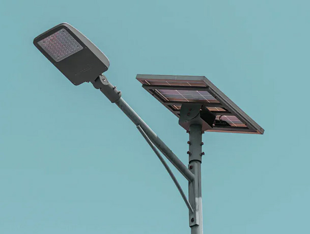
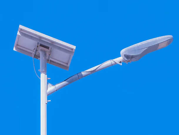
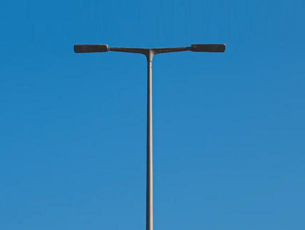
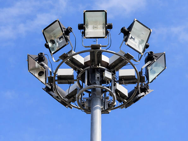
Worked example: with H = 30 m, h = 12 m and d = 20 m, s = 20 × 12 ÷ (30 − 12) = 13.33 m. A source at 20 m gives 30.00 m; a source at 40 m gives 8.57 m. These are assumed geometry inputs, separate from the photographs.
↔ Swipe to read all columns.
| Light height H | Obstruction height h | Distance to edge d | Shadow beyond edge s |
|---|---|---|---|
| 20 m | 12 m | 20 m | 30.00 m |
| 30 m | 12 m | 20 m | 13.33 m |
| 40 m | 12 m | 20 m | 8.57 m |
| 30 m | 6 m | 20 m | 5.00 m |
| 30 m | 9 m | 20 m | 8.57 m |
The comparison holds distance and stack height fixed in the first three rows. At a ground point 40 m from the source, the ray crosses the stack position at H ÷ 2: 10 m for the 20 m source and 15 m for the 30 m source. A 12 m obstruction blocks the first ray and clears the second. Increasing lumens at the first position does not change its ray path.
This two-dimensional screen model ignores finite stack width, gaps, nearby rows, reflected light, multiple floodlights and real luminous-intensity distributions. A geometric shadow is a zone without direct contribution from this source, not a prediction of zero measured lux. Greater mounting height also changes distance, incidence and glare. Use actual IES or LDT files and a three-dimensional layout to evaluate those effects; the table does not select a mast height or establish compliance.
Horizontal pavement values help assess routes and ground work. Container identification, coupling areas and inspection faces may involve different heights and orientations. Define each task with the operator and designer, then record the required receiving plane and criterion. A high average over a whole storage block can conceal a poor result along its occupied edge.
↔ Swipe to read all columns.
| Task / location | Plane or view to define | Evidence to request |
|---|---|---|
| Vehicle lane and crossing | Required pavement grid plus driver eye positions | Local minimum, uniformity definition and glare review |
| Container identification / inspection | Relevant vertical face and reading direction | Calculation or survey on the defined task surface |
| Handling and transfer point | Changing load and equipment envelope | Occupied-state review and any supplemental task lighting |
| Pedestrian access beside stacks | Route surface and approach views | Continuity through shaded segments and transitions |
A useful jurisdiction-specific example is US OSHA 29 CFR 1917.123. It sets an average minimum of 5 foot-candles for active work areas, with stated exceptions and provisions for other work and security areas. Five foot-candles converts to approximately 53.8 lx using 1 foot-candle = 10.7639 lx. Its measurement provision places the detector on the actual task surface and in its plane. This is a US regulatory example, not a universal container-yard design target; the applicable authority and project task schedule determine the requirements. [1]
Port Skills and Safety’s SiP009 v2, published October 2025, discusses cargo shadows, contrast changes and glare. It is UK-context guidance. Its survey recommendations support recording operating conditions so a later team can understand what was assessed. Do not use a general guidance reference to assign one lux value to every terminal task. [2]
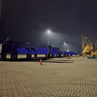
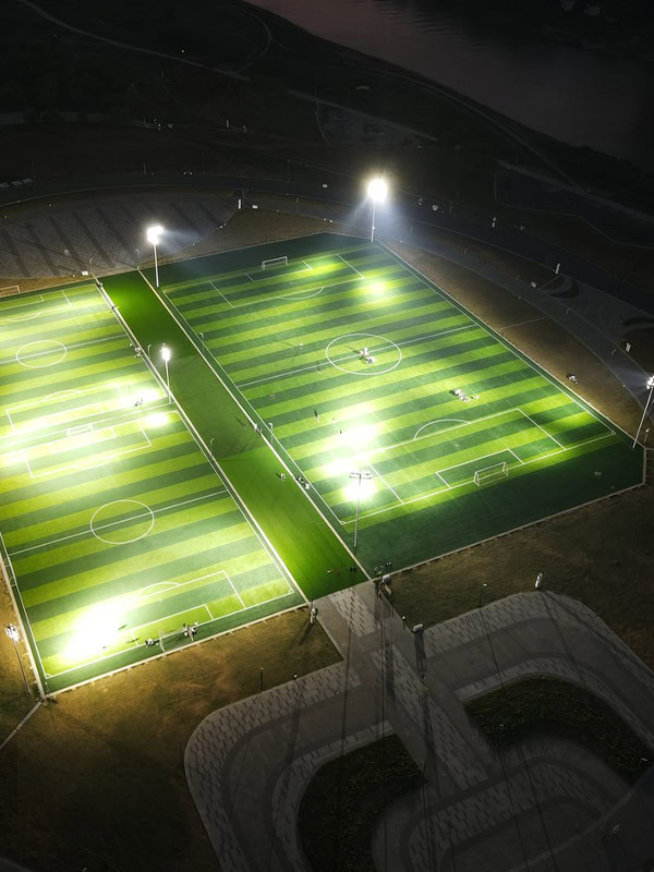
Lighting across a paved terminal working area — an application example.
Ask the designer to show where each important working zone receives light from. Lighting from another direction can reach behind an obstruction, but the alternate path may itself be blocked by the next row. More mast positions can also introduce bright sources into a crane or vehicle operator’s view. Compare these effects in the occupied model rather than assuming that cross-lighting always resolves the problem.
Keep structural and operational constraints in the same option review: equipment clearance, vehicle-impact protection, foundation locations, access to the lowering ring and the temporary area needed for servicing. A mast position that works photometrically may obstruct handling operations or have no usable maintenance space. The high mast lighting system should be specified with those interfaces.
Controls need the same operating-state discipline. Check how an inactive storage block returns to service, which routes stay lit and what happens if a sensor or communications link fails. Compare power and hours after the options meet the agreed lighting service. The existing port guide covers energy arithmetic; this article’s calculation isolates stack obstruction.
Before the night survey, record the luminaire/optic schedule, aiming revision, active scene, stack heights, equipment positions and weather or surface conditions relevant to the measurement. Use the approved grid and task planes with an identified, suitably calibrated meter. Photograph the obstruction state alongside its plan reference; a lux sheet with no stack record is difficult to reproduce later.
Review critical route segments and operator views with the terminal team. Preserve readings and observations before corrective aiming, then record the revised configuration and retest. If a later yard plan increases stack height or moves an aisle behind a row, review the affected light paths. A survey for the earlier geometry does not establish performance for the revised layout.
Two-page planning and verification record
Record stack states, task planes, the geometric example and the evidence needed for a lighting comparison.
Download the container-terminal lighting worksheet · PDF
Height can shorten the ideal ground shadow from one edge, as the example shows. Real rows, source locations, optics and task planes still need checking. The decision belongs to the full layout comparison.
Use the criteria and reporting zones required for the tasks. A site-wide average alone does not describe the shaded lane, the vertical reading face or the driver’s view.
Send the terminal plan, normal and maximum stack envelopes, handling equipment, traffic routes, operating scenes and required task criteria. Include pole-height constraints, exposure, maintenance access and any existing photometric files. Jieyao Lighting can discuss the pole, mounting and lighting package against that brief; share the layout and project requirements.
[1] US OSHA, 29 CFR 1917.123, Illumination: scope, active work areas, measurement plane and glare. https://www.osha.gov/laws-regs/regulations/standardnumber/1917/1917.123
[2] Port Skills and Safety, SiP009 Guidance on Lighting, v2, October 2025: cargo shadows, working areas, controls and surveys. https://www.portskillsandsafety.co.uk/wp-content/uploads/2023/11/SiP009-Open-access-version.pdf
References accessed 10 November 2026. The shadow table is Jieyao’s original arithmetic under the stated ideal assumptions. The downloadable worksheet reproduces the formula and inputs. Photographs illustrate applications; the calculation is not a measurement of those scenes.
Published 10 November 2026 · Yangzhou Jieyao Lighting Equipment Co., Ltd.
Contact Us
Get a custom lighting solution and quotation for your project. Yangzhou Jieyao Lighting Equipment Co., Ltd. manufactures outdoor lighting and steel poles in Guoji Town Industrial Park, Gaoyou City, Yangzhou, Jiangsu, China. The company reports a 10,000 m² factory site, more than 60 employees including more than 10 technical personnel, and more than 100 production and testing machines. The present company name dates from 2017; Jieyao Poles’ published history traces the team’s manufacturing lineage to 2006. The stated 15 years of experience refers to the team. The company reports exports to more than 60 countries. Do you have any questions or requests?
Email: jay@jieyaolighting.com

Click to Chat.
Im online now.
 English
 Español
 Bahasa Indonesia