

A useful 5G smart pole specification identifies exactly which equipment is mounted, where it is mounted, who supplies it, how its loads reach the pole and foundation, how power and data enter, and who can service each compartment. “5G-ready” is not a complete structural or utility design. The radio, antenna, luminaire, cabinet, camera and future allowance must be listed by model or defined design envelope, with mass, wind-facing data, dimensions, power, heat and cable needs supplied by the responsible equipment owners.
The pole fabricator can then develop a coordinated structural and fabrication proposal against an approved design basis. The telecom operator remains responsible for its RF, network, service and security decisions unless the contract expressly assigns a different scope. Lighting photometrics, civil foundations, electrical protection and utility permits also require their respective project owners. Avoid assuming that buying a smart pole includes a working mobile network or all connected devices.
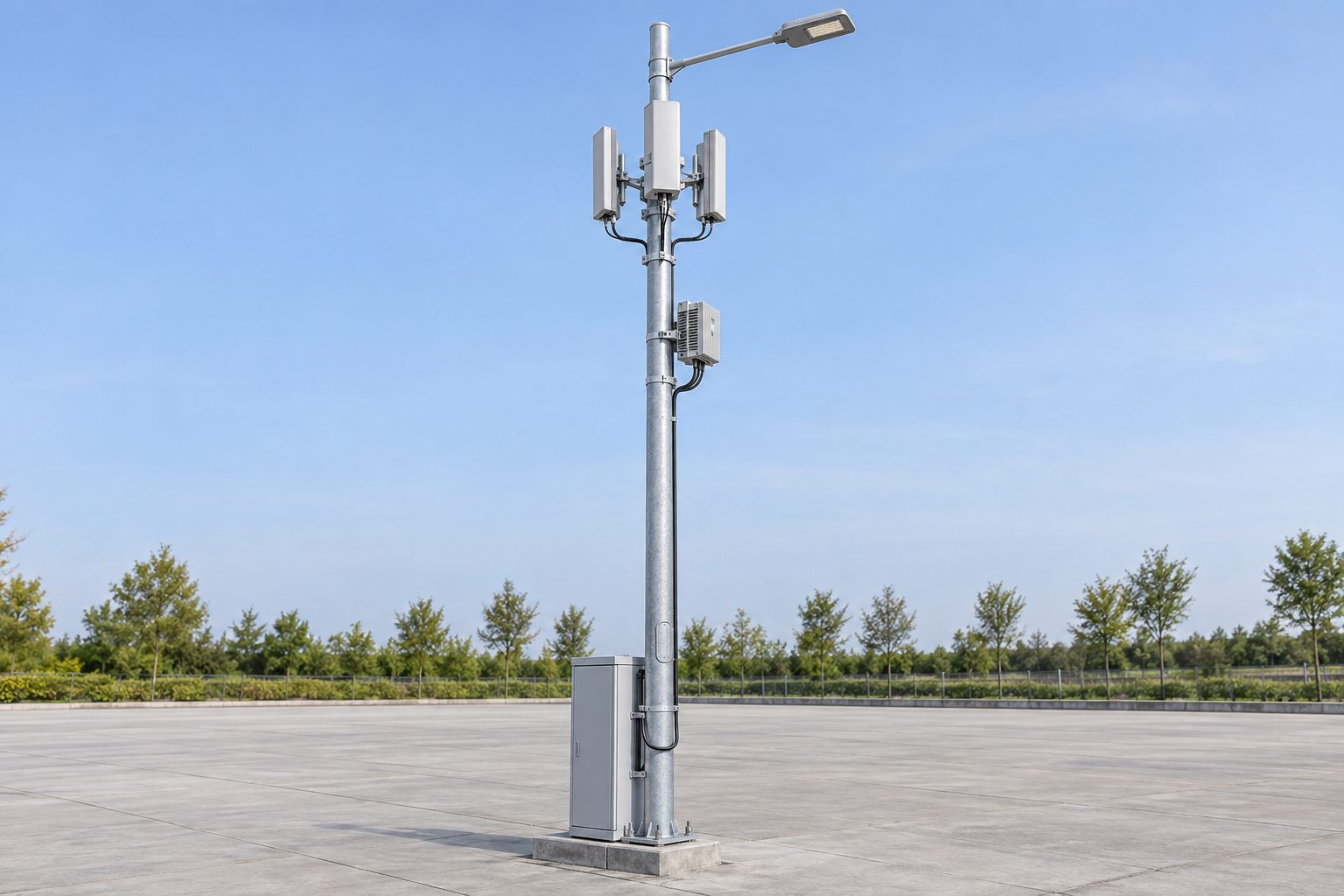
Start with an elevation and plan that locate every antenna, radio unit, luminaire, optional camera, cabinet and service opening. Identify mounting height, azimuth, bracket reach, cabinet dimensions, equipment mass and the projected-area data required by the governing structural method. Antenna panels and radios should have independent, serviceable mounting details rather than being placed on a generic “spare bracket.” Define whether future equipment is excluded or included in a quantified allowance. The design envelope must be reviewed again when the equipment model changes.
The equipment owners should coordinate RF clearances and access zones with luminaire reach, road setback and worker access. A bracket that physically fits may still obstruct a service door, conflict with a luminaire arm or leave inadequate maintenance space. The shop drawing should show the pole, brackets, openings, cabinet and cable-entry paths in the same revision. For the broader drawing process, see the street light pole shop drawing checklist.
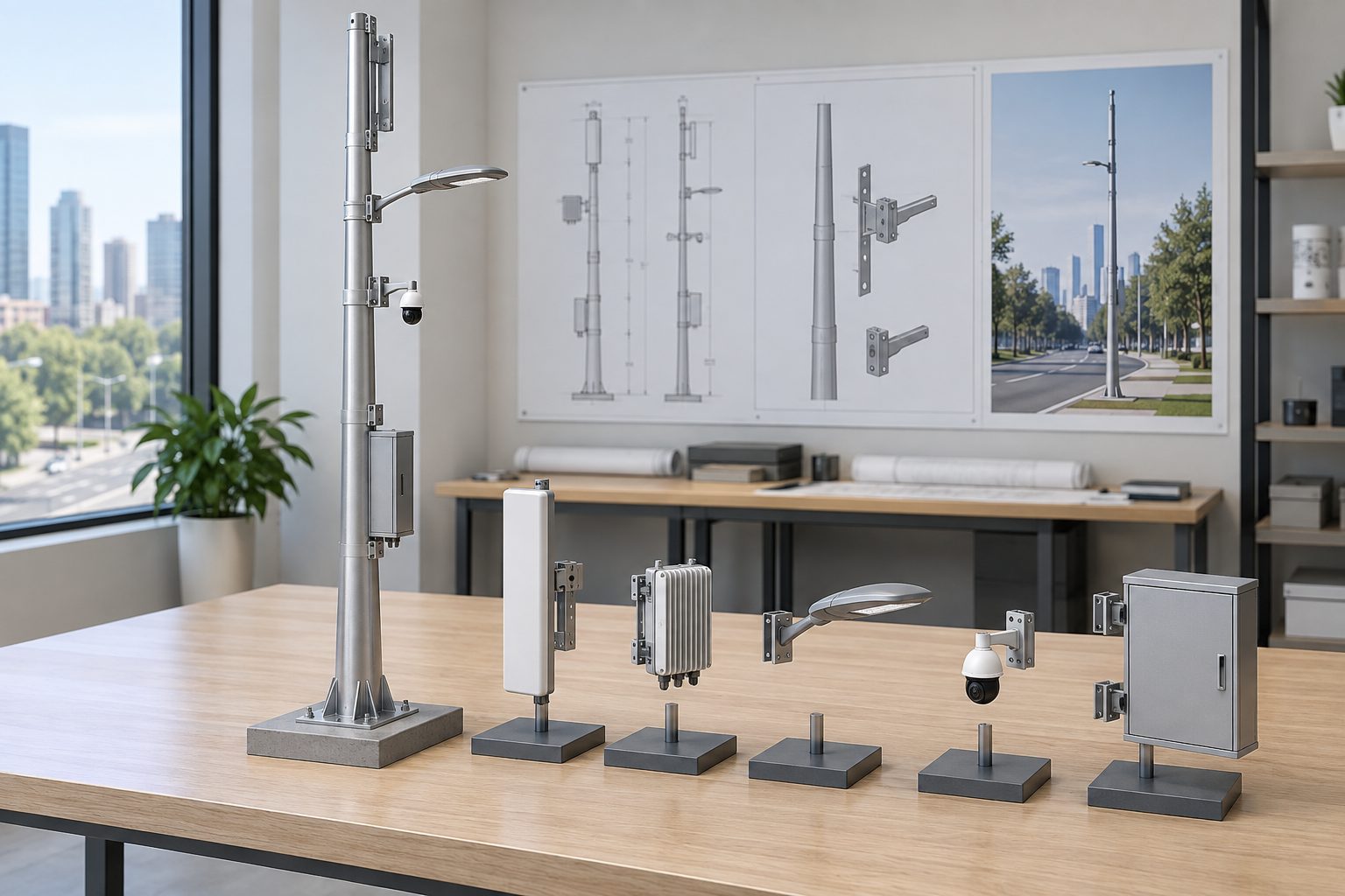
This table is a scope-allocation worksheet, not a claim that one supplier performs every task. Mark the named party and deliverable for the actual project. A blank owner is a coordination risk, especially where structural brackets meet operator-provided hardware or where power and fiber share a civil route.
| Interface or deliverable | Decision that must be recorded | Typical party to identify in the contract |
|---|---|---|
| Pole and brackets | Shaft, attachment details, access openings, finish, fabrication documents | Pole supplier / structural designer |
| Radio and antennas | Exact models, orientations, RF zones, mass, wind data and mounting hardware | Telecom operator / equipment owner |
| Roadway luminaire | Model, arm fit, optical aim, load and electrical connection | Lighting designer / luminaire supplier |
| Power and protection | Service point, distribution, earthing/bonding, isolation and metering | Electrical engineer / utility |
| Fiber and data | Conduit, demarcation, bend/entry requirements and service access | Network owner / telecom contractor |
| Cabinet and thermal needs | Size, ventilation/heat assumptions, door swing and replacement access | Equipment owner / mechanical-electrical designer |
| Foundation and permits | Reactions, anchors, conduit exits, site access and approvals | Civil/structural designer and local authority |
The schedule should explicitly state whether a camera or sensor is in this order. A structural placeholder does not authorize a later attachment without checking its mass, wind data, mounting and power/data route. Likewise, changing an antenna or radio can affect both the structural model and the cable/thermal layout. Record who approves substitutions and what evidence is needed before installation.
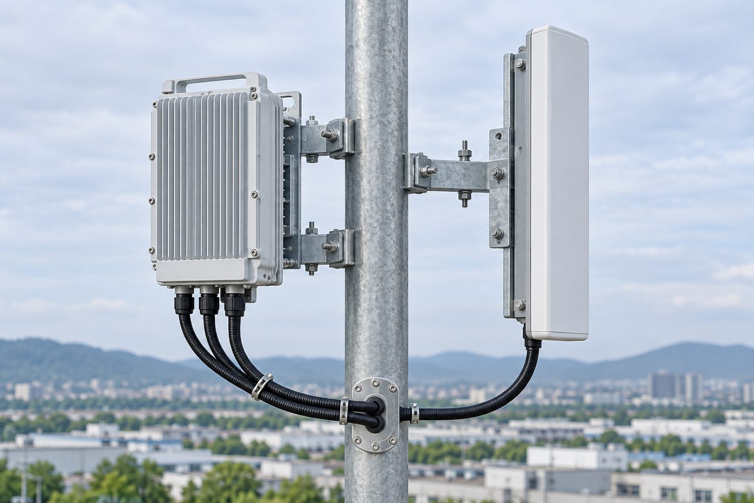
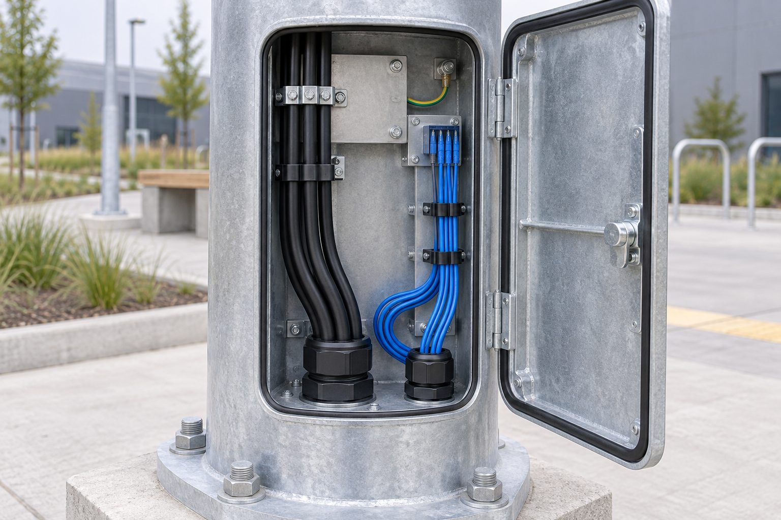
Show incoming power, protective earth, fiber/data and spare conduits on a coordinated base and internal routing drawing. The electrical and network designers should define separation, protection, termination, bend space and demarcation to suit their equipment and applicable rules. The pole service opening must allow inspection and replacement without cutting a structural member or exposing another owner's equipment unnecessarily. Do not claim a particular IP rating, thermal performance or cybersecurity feature unless a specified enclosure and test evidence support it.
Ask for maintenance reach at each mounted device, door swing, lock ownership and the isolation procedure that lets a technician work safely. An antenna may be mounted high while the associated radio or power unit sits in a lower cabinet; the cable route between them must be feasible, protected and traceable. The pole access-door and cable-routing guide explains the basic steel-pole access interface, while the 5G package needs a project-specific utility layout.
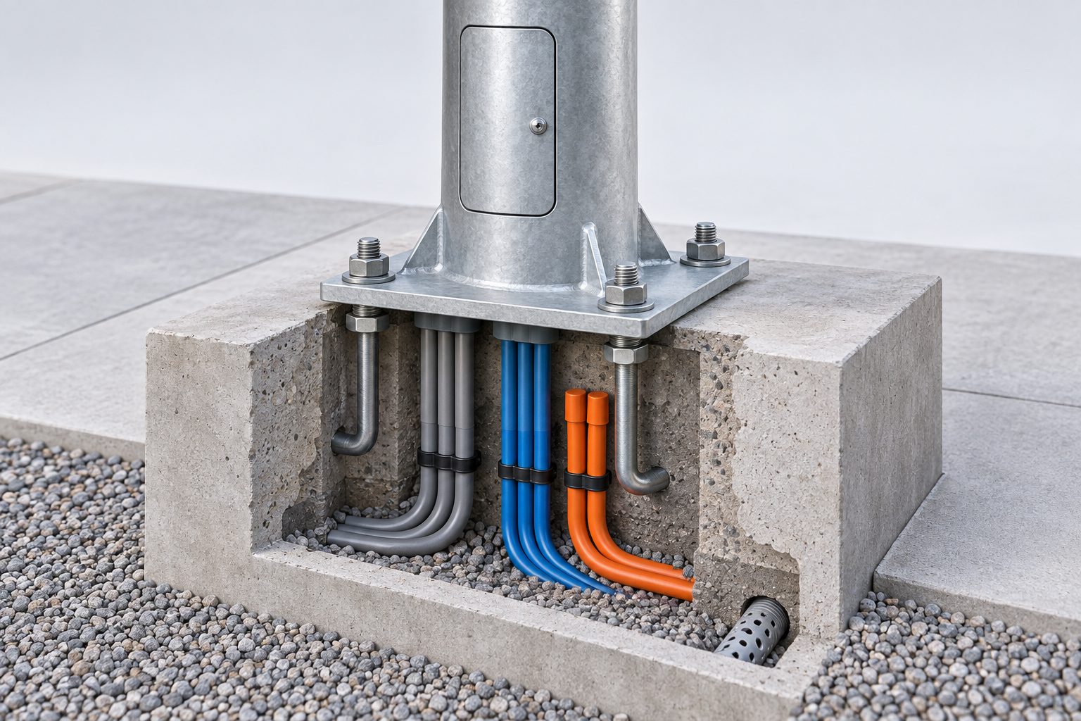
The structural designer needs the pole geometry, complete mounted equipment schedule, applicable site wind basis and any project-specific fatigue or dynamic requirements. The resulting base reactions and anchor arrangement must be coordinated with the civil engineer's foundation, soil assumptions, conduit exits and erection access. A drawing that shows an anchor circle but omits the reactions does not fully release the foundation interface. Nor can a previous lighting-only pole calculation automatically validate new radio equipment. The foundation and anchor-bolt guide covers this handoff in greater detail.
The second table is an information-to-review matrix. It differs from the responsibility table by showing what the buyer must send and which result should be returned before an order proceeds. “TBD” values should be flagged rather than silently assumed.
| Buyer input to issue | Why it is needed | Expected review output |
|---|---|---|
| Site, governing design basis and permit constraints | Establishes structural/civil envelope and location | Design criteria register and interface assumptions |
| Equipment list with mass, wind and mounting data | Defines shaft, bracket and anchor loads | Controlled load schedule and structural check |
| Power, fiber and cabinet schedule | Defines opening, conduit and service space | Utility routing and compartment drawings |
| Lighting layout and luminaire model | Defines arm fit and optical coordination | Arm/luminaire interface and approved photometric responsibility |
| Finish, access and maintenance requirements | Defines corrosion system and replaceable parts | Coating/access drawings and inspection plan |
| Document and acceptance requirements | Defines review, inspection and handover scope | Submittal register and release checkpoints |
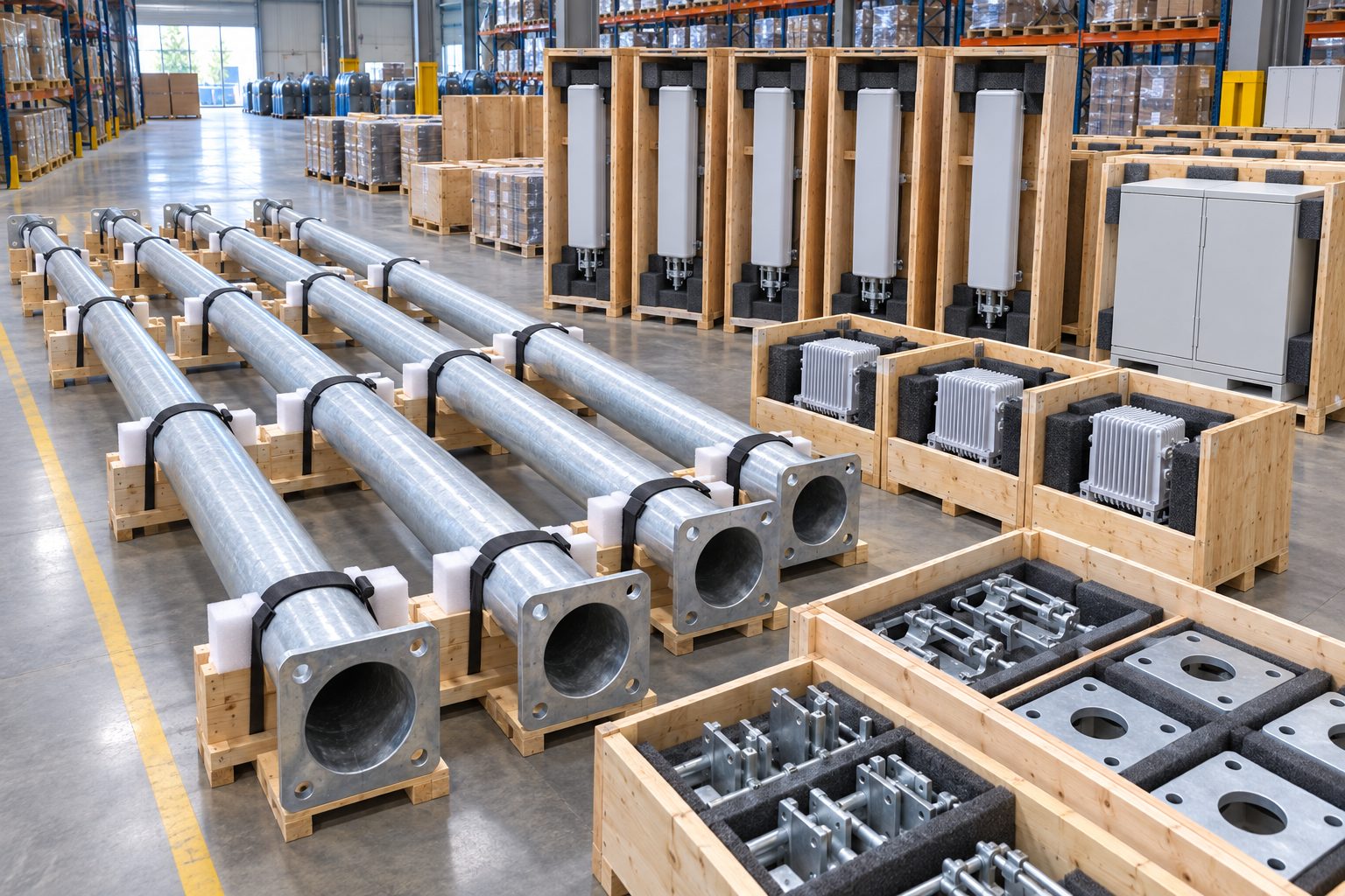
For export or multi-contractor work, identify how matched shafts, brackets, doors, equipment mounts and anchor templates are marked and protected. Keep operator-supplied electronics separate from the pole supplier's packing scope unless the contract says otherwise. The factory acceptance checklist can support the steel assembly review, but it does not replace telecom commissioning.
No. The pole, brackets, radio, antennas, cabinet, lighting, network and installation scopes must be identified in the quotation and contract.
It may be feasible, but each device needs a documented position, load, access and power/data route. The project engineer and equipment owners must approve the combined arrangement.
No. State the actual equipment or a bounded future allowance with mass, wind-facing data, mounting elevations and bracket geometry.
The telecom operator or its appointed specialist. A steel-pole specification cannot promise coverage, throughput or service availability.
Send the site and design basis, equipment schedule, mounting and utility drawings, foundation constraints, maintenance access, finish and required deliverables. Contact Jieyao for a pole/interface proposal based on those controlled inputs.
Contact Us
Get a custom lighting solution and quotation for your project. Outdoor lighting manufacturer in Yangzhou, ChinaAbout Jieyao LightingYangzhou Jieyao Lighting Equipment Co., Ltd. is an outdoor lighting manufacturer focused on solar street light systems and high mas... Do you have any questions or requests?
Email: jay@jieyaolighting.com

Click to Chat.
Im online now.