

Commission a high-mast lighting system against its approved site layout and photometric calculation, not by pointing every floodlight toward the brightest visible patch. Confirm the installed mast and head-frame coordinates, exact luminaire/optic schedule, aiming reference, control scenes and safe access method. Aim and lock each fitting under the designer's approved procedure; then observe the relevant task areas and neighboring receptors in the agreed night conditions. Record deviations, corrective changes and retests. A high-mast installation is not accepted merely because all lamps turn on or because a photograph appears bright.
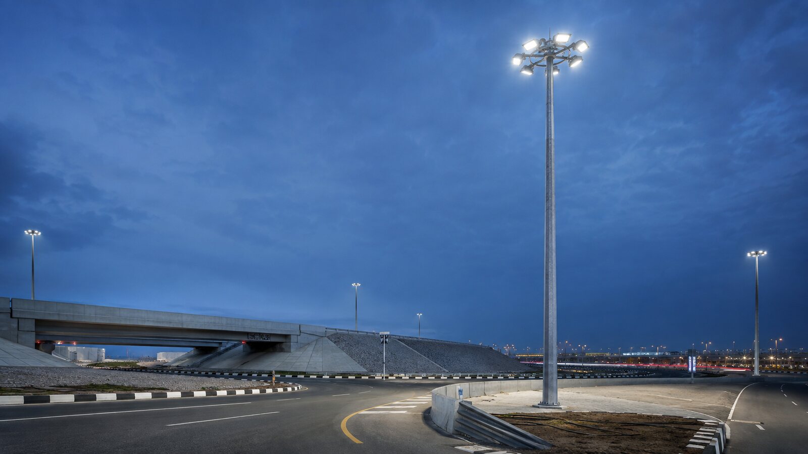
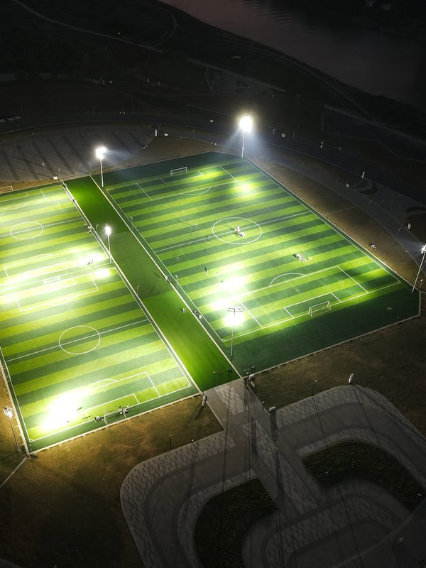
A wide site view locates task areas and approaches, but it cannot substitute for an identified observation point or measurement record.
The commissioning team needs one controlled drawing set: mast IDs and coordinates, head-frame orientation, luminaire positions, model and optical variant, aiming angles or targets, mounting hardware and the calculation revision. Record the approved site boundaries, work zones, road or vehicle approaches, pedestrian paths, nearby properties and any protected or sensitive directions. The designer should state the applicable criteria and measurement/observation methods for each task. A port yard, highway interchange and sports-area perimeter cannot share a generic floodlight aiming rule. The highway-interchange pole-versus-high-mast comparison addresses the earlier system-selection decision, not this field-acceptance stage.
Before energizing, qualified staff should verify that the structural, electrical and access releases required by the project are in place. Aiming brackets must be secured as specified, and raising/lowering equipment—where fitted—must be used under its separate approved operating procedure. This guide describes the evidence and coordination sequence; it does not instruct unqualified workers to handle energized gear or work at height.
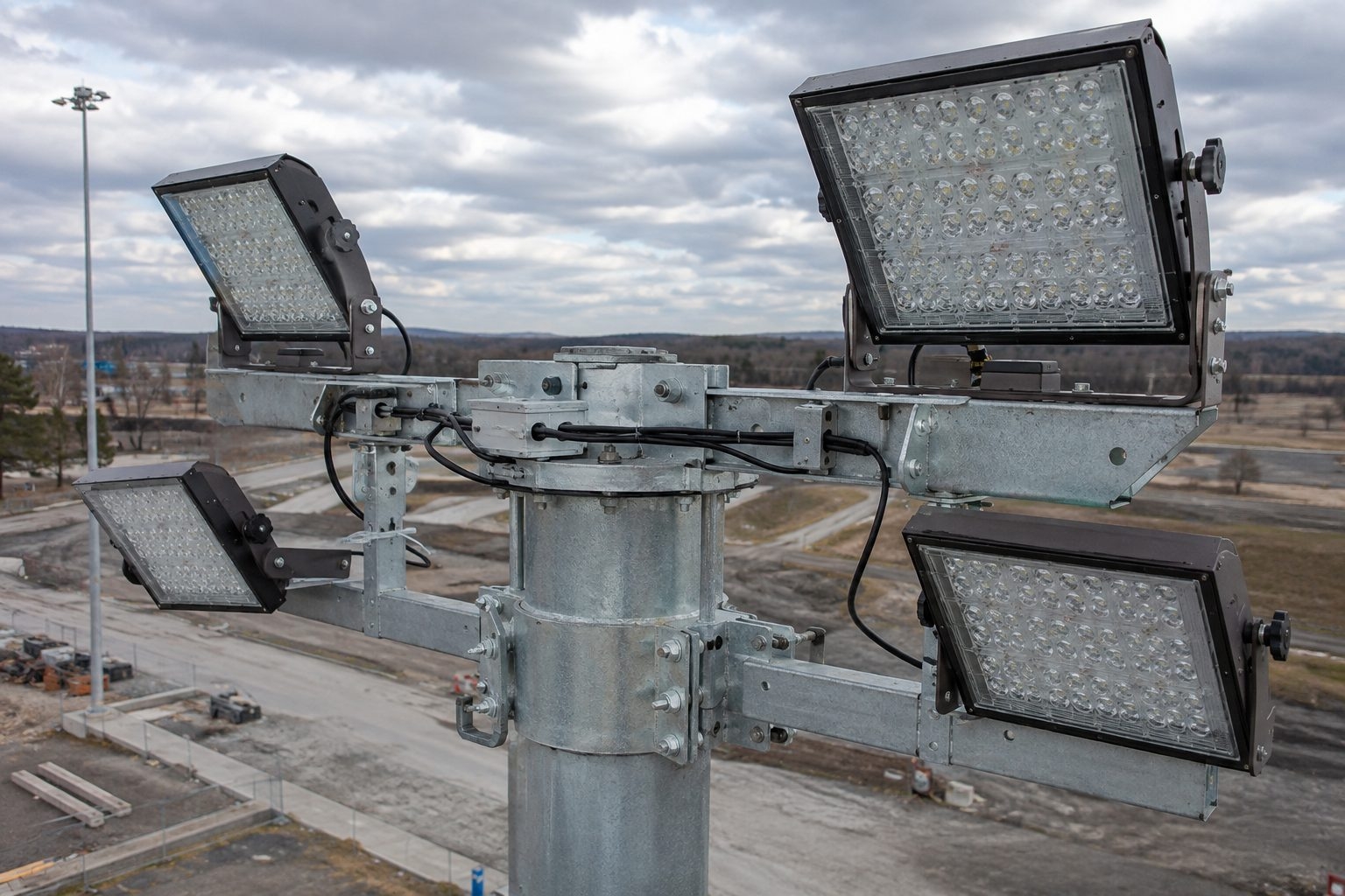
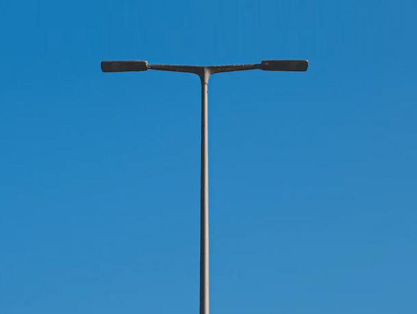
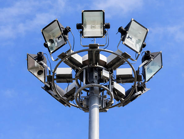
The fitting and bracket positions need an asset-specific aim reference; the image alone does not identify a passed setting.
| Pre-aim input | Record to freeze | Why it matters |
|---|---|---|
| Mast and head-frame | Mast ID, location, elevation, frame orientation and fitting positions | A rotated or relocated frame changes the planned distribution. |
| Luminaire schedule | Exact model, optic, output setting, driver and control group | A substitute fixture may invalidate the calculation. |
| Aiming basis | Designer's target, angle convention, reference direction and lock method | Different crews must reproduce the same approved intent. |
| Operating scenes | Full, reduced, event and fallback states as applicable | Glare and task visibility can change with controls. |
| Receptors and tasks | Work area, approach views, neighboring windows or boundaries | Spill and disability/discomfort concerns need named observation points. |
Use the approved drawing to identify each luminaire and its intended direction. Record the starting aim and any change with a clear angle convention or marked physical reference so future maintenance can reproduce it. Where the system has multiple floodlight groups, commission them in an agreed sequence and avoid losing track of which fitting was adjusted. A night photograph may document context, but exposure, white balance and viewpoint can make brightness look different; it cannot replace a defined measurement or observation record.
If the team finds a dark task area or spill toward a neighboring property, first compare the installed layout and control scene with the approved model before changing several lights. A blocked view, incorrect optic, changed mast position or control setting may be the root issue. Record any field aiming change on the as-built drawing and obtain the designer's acceptance where the change affects calculations, glare, structural clearance or neighboring receptors. Do not cure a layout mismatch by unrecorded over-aiming.
Glare is not a single number inferred from the floodlight wattage. The authority or lighting designer should define the relevant metrics and observation positions for the application. Check the intended task from operator viewpoints and examine approach directions, high-angle views, perimeter lines and adjacent properties identified in the design. Aiming that makes the center of a yard brighter may put direct light into a driver, crane operator or neighbor's line of sight. Conversely, a dark-looking photograph does not prove the design criterion is missed.
The observation should be made under the accepted operating scene and reasonably recorded ambient conditions. Note weather, neighboring light sources, equipment that blocks the beam, and any temporary work-light contribution. Where a formal photometric field test is specified, document the instrument, calibration, grid, operating condition and reviewer. Do not substitute a visual walk-through for a required measured acceptance test. Any nearby transport, aviation or environmental restriction must be reviewed by the relevant authority; this page does not declare universal compliance.
| Commissioning check | Evidence to keep | Hold or corrective action |
|---|---|---|
| Installed identity | Mast/frame IDs, fitting model/optic and as-built position | Resolve a wrong optic or rotated frame before acceptance. |
| Aiming setting | Before/after reference, bracket lock and authorized adjustment | Recalculate or seek approval if the field aim differs materially. |
| Task performance | Agreed observation and measured results where specified | Correct dark zones against the design, not by guesswork. |
| Glare and spill | Named receptor/viewpoint, scene, conditions and findings | Re-aim, shield or redesign with responsible approval. |
| Controls and fallback | Scene commands, actual output and fault behavior | Hold handover if a mode defeats the intended task. |
| Final record | Defect list, retest, drawing revision and owner sign-off | Keep open exceptions visible rather than marking an incomplete system done. |
At handover, give the operator the final aim schedule, luminaire/optic identities, scene settings, measurement records, access instructions and permitted adjustment procedure. A later replacement must match the approved optic, output and mounting orientation or be reviewed as a design change. If a lift, sign, new building or tree growth changes the task area or a neighbor's view, reopen the lighting review instead of relying indefinitely on the original aiming photograph.
Where a raising-and-lowering head frame is used, confirm that the final stowed and service positions do not disturb aim or cable routing under the approved mechanical acceptance procedure. The raising/lowering versus fixed-head guide explains that access-system choice; mechanical verification remains separate from the optical commissioning described here, and neither test replaces the other.
No. Follow the approved optic and aiming schedule. The layout must serve the actual task area and control glare/spill at the relevant viewpoints.
No. It helps document context but is sensitive to exposure and viewpoint. Use the agreed observation and measurement method with identifiable scenes, fittings and test conditions.
The authority or designer named in the project approval process. Record the change and its effect on task performance, glare, spill and any applicable restrictions.
The mast and fitting IDs, exact luminaire/optic, approved aim reference, bracket setting, scene configuration, inspection method and revision-controlled as-built drawing.
Contact Us
Get a custom lighting solution and quotation for your project. Outdoor lighting manufacturer in Yangzhou, ChinaAbout Jieyao LightingYangzhou Jieyao Lighting Equipment Co., Ltd. is an outdoor lighting manufacturer focused on solar street light systems and high mas... Do you have any questions or requests?
Email: jay@jieyaolighting.com

Click to Chat.
Im online now.