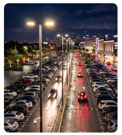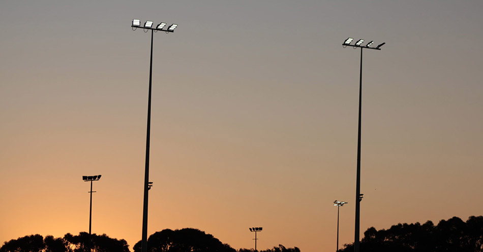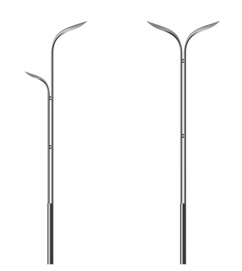


Plan pole height, spacing, head arrangement and protected locations from the real parking geometry, photometric model, fixture data and maintenance strategy.
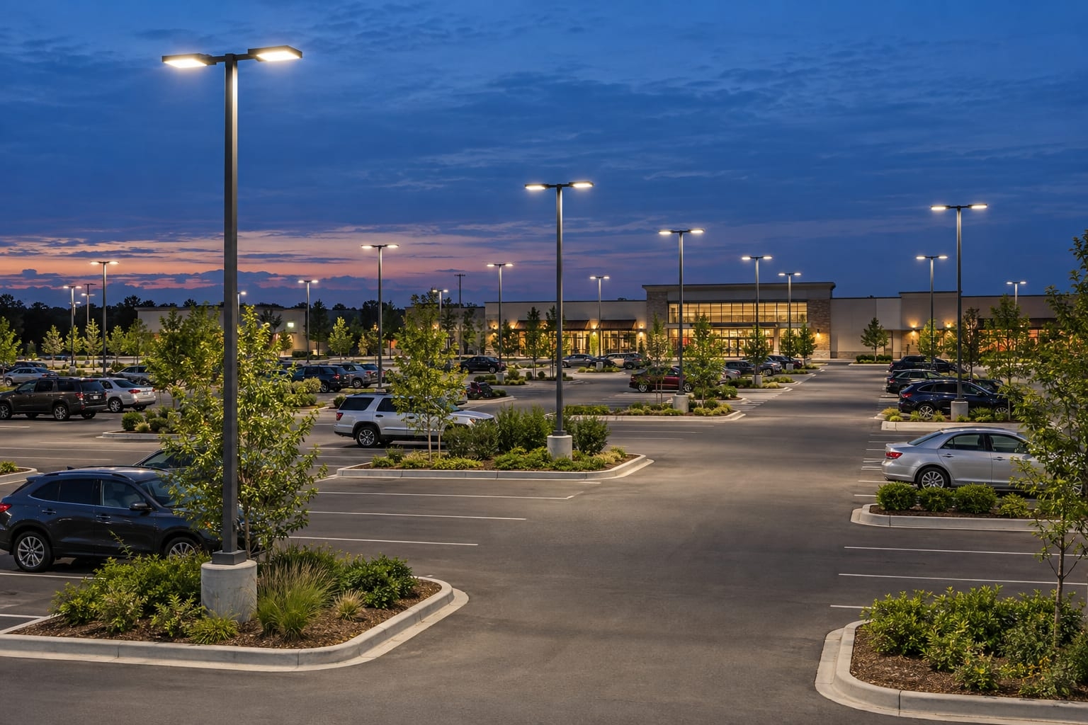
A parking facility contains bays, drive aisles, turning areas, accessible routes, entrances, building edges and landscape islands. Pole height and spacing cannot be selected from one area dimension. The design must connect lighting criteria, actual fixture distribution, pole coordinates, structural loads, foundation conditions, vehicle protection and future service access.
This guide explains that coordination without publishing universal height, radius or spacing values. Final requirements follow the project authority, applicable lighting standard, site geometry and approved calculations. The page stays focused on parking-area intent; use the broader outdoor lighting pole selection guide for campuses, landscapes and commercial precincts.
Use the latest civil or architectural layout showing bay markings, aisle directions, curbs, islands, pedestrian crossings, accessible spaces, ramps, stairs, entrances, loading zones and finished levels. Add buildings, canopies, walls, trees and utilities that can block light or restrict foundations. A simplified rectangle hides the conditions that normally control pole placement.
Confirm dimensions and drawing revision before modeling. If the parking plan is still changing, identify provisional zones and repeat the affected lighting study after updates. Do not freeze foundations from an early layout while using a later parking arrangement for photometric approval. Common coordinates and revision marks keep lighting, civil and procurement teams aligned.
State the project classification, calculation method, target quantities, uniformity measures, maintenance assumptions and limits on glare, spill or obtrusive light. Different jurisdictions and properties can use different criteria. A single ratio copied from another parking lot is not a reliable design basis without the governing context.
Separate relevant zones where the brief requires it: parking stalls, drive aisles, pedestrian paths, entrances, loading points, ticket or payment areas and adjacent boundaries. Review minimum and average results, transitions and vertical surfaces where applicable. A high average can coexist with dark gaps, excessive bright spots or unacceptable light toward windows.
The model should use the proposed luminaire's current photometric file, output, optic, tilt and orientation. Wattage does not describe light distribution. Fixtures with similar electrical input can produce different longitudinal reach, lateral spread, cutoff and glare. A change in optic or fixture model can alter the preferred height, spacing and pole line.
Match the optical coordinate to the physical pole drawing. State tenon or spigot size, bracket direction, mounting angle and fixture center. For multi-head poles, model every head at its installed orientation. If the fixture is substituted, recheck photometrics, mass, projected area, center of gravity and mounting compatibility before approval.
Height influences the elevation and apparent coverage of the light distribution; spacing controls how adjacent distributions overlap. A taller arrangement may suit an open area with the right optic, yet changes visual scale, equipment reach and structural demand. A lower arrangement may provide closer control but require more foundations, cable routes and pole locations.
Compare complete options on the same site and criteria. Record changes to height, spacing, optic, output, tilt and head arrangement. There is no universal rule that spacing equals a fixed multiple of mounting height. Use the calculation output and site conflicts to select an arrangement, then preserve that exact option in the drawings.
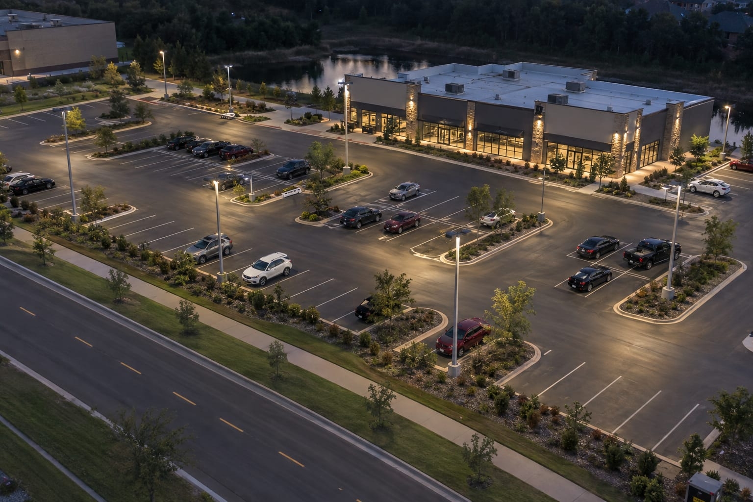
Perimeter poles can keep equipment away from central vehicle movement, but may increase the distance to interior areas or direct light toward adjoining property. Interior poles can shorten optical reach and support symmetric multi-head arrangements, yet require protected islands, foundations among utilities and safe maintenance access. Neither pattern is automatically best.
Irregular sites often use a controlled combination. Test each pole line against the real calculation grid, vehicle swept paths and boundary conditions. Avoid placing an interior pole merely to fill a dark point if the location conflicts with a pedestrian crossing, drainage inlet or future tree. Revise the complete option instead of treating pole placement as isolated dots.
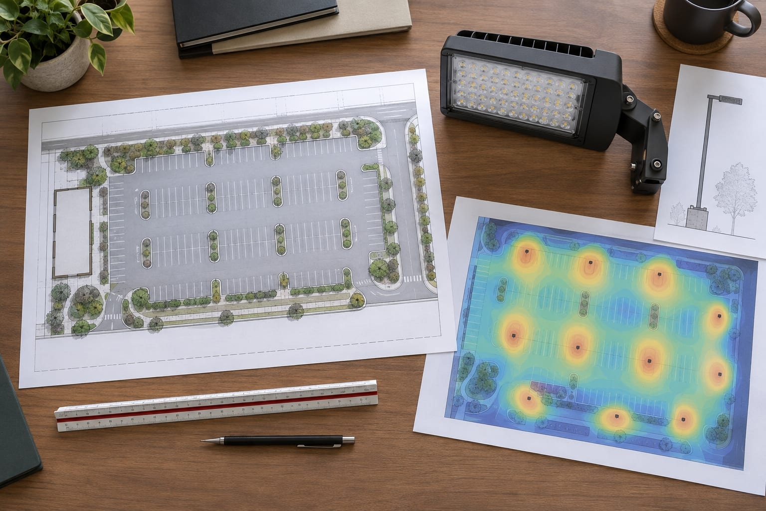
Compare placement patterns against the same luminaire photometric file and complete site plan. The table distinguishes likely review points; it does not prescribe a universal pole count, coverage radius or best layout.
| Pole-line option | Lighting question | Civil/operation check |
|---|---|---|
| Perimeter | Interior uniformity and spill toward neighbors | Boundary foundation, utilities and service reach |
| Interior islands | Multi-head aiming and overlap across drive aisles | Vehicle impact protection, accessible routes and drainage |
| Combined lines | Whole-site grid and transitions between pole families | Distinct pole marks, cable circuits and spare-parts planning |
Locate poles inside designed islands, behind curbs or barriers, or beyond vehicle swept paths as the civil layout allows. Consider passenger cars, delivery vehicles, refuse collection, fire access, snow clearing and maintenance equipment. A painted line does not provide physical protection, and a pole placed at the end of a bay can be exposed to overhang or reversing impact.
Protection must not create another hazard. Coordinate curb geometry, bollards, accessible routes, sight lines and door access. The foundation and base should remain inspectable and should not trap water or landscape debris. Show the relationship on the site detail rather than relying on a generic note to “protect pole.”
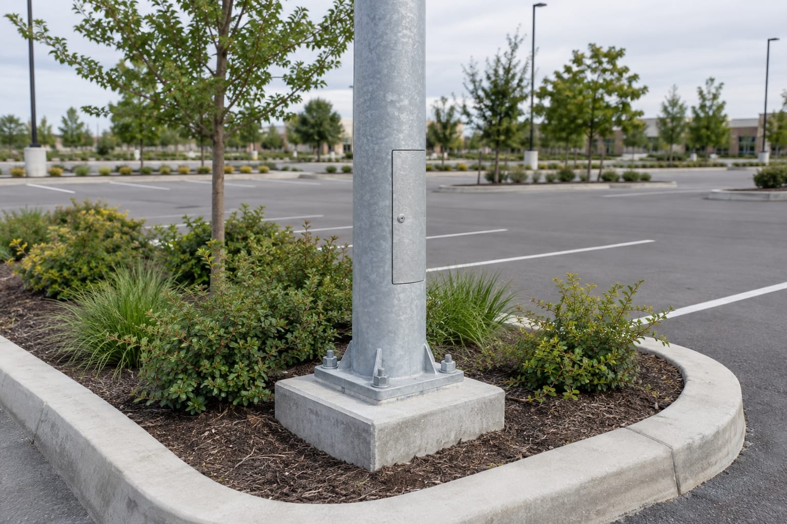
Accessible parking spaces, access aisles, curb ramps and pedestrian paths require clear width and unobstructed movement. Coordinate local accessibility requirements before fixing pole or foundation positions. Base covers, anchor projections and open service doors should not reduce the intended route or create trip and collision points.
Consider how pedestrians travel from every parking zone to entrances, not only the marked crossing. Lighting should support those routes without placing structures in them. If a pole is moved to protect accessibility, update the photometric model, cable route and foundation information; do not keep the old calculation coordinates.
Drivers experience rapid changes in view and brightness at entrances, exits, ramps and payment points. Model the relevant observer directions and check the selected fixture distribution, tilt and shielding. Raising a pole does not automatically eliminate glare, and lowering it does not automatically improve comfort. The installed optical position controls the result.
Keep poles clear of signs, gates, canopies, sight triangles and turning paths. Coordinate with public-road lighting and nearby signals where the project requires it. Boundary-facing fixtures may need different optics, shields or orientations from interior heads. Record those variations as controlled pole or luminaire types.
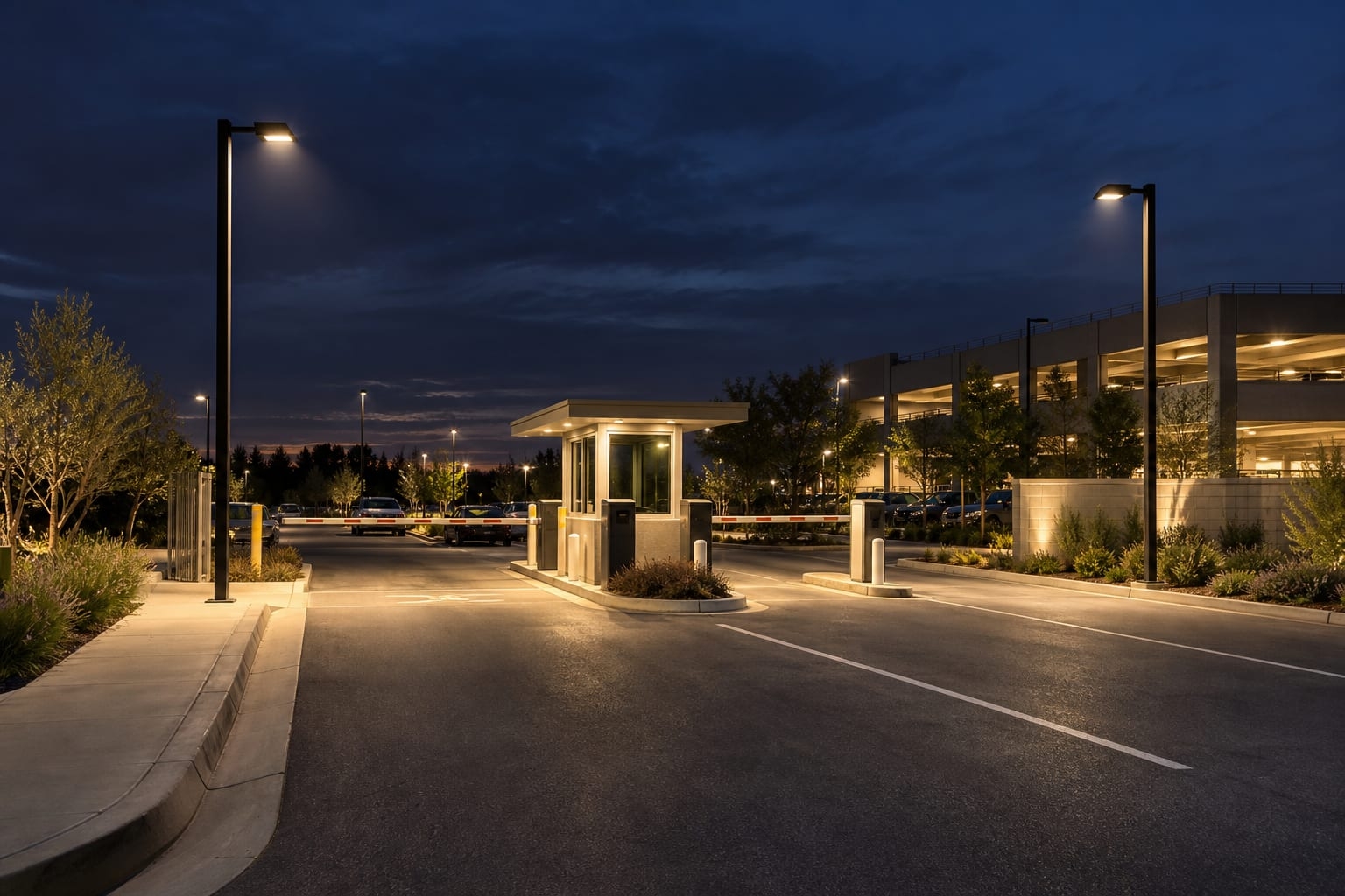
Adjacent homes, hotel rooms, offices, roads and environmental areas may impose limits on light beyond the site. Include boundary calculation points and relevant vertical planes when required. A strong interior result does not justify uncontrolled backlight or high-angle intensity outside the parking area.
Pole setback, fixture orientation, optical distribution, tilt, output and shielding work together. Compare those variables before changing height alone. Note any shield or aiming restriction in the luminaire schedule and drawing because it affects photometric output, equipment load and installation verification.
Landscape islands often contain both trees and poles. Model mature canopy size and keep luminaires, doors and maintenance equipment clear of branches. Coordinate foundations with root zones and irrigation. A small newly planted tree can become a major obstruction if the lighting layout only represents the opening-day condition.
Building projections, covered walkways, solar canopies and loading shelters create shadows and restrict pole positions. Combine pole-mounted and building-mounted equipment only after comparing the complete pattern. Do not assume additional wattage will compensate for an obstruction; use appropriate placement and optics.
Twin, triple or four-way arrangements can serve several parking zones from one protected location. Every head needs a defined orientation, mounting interface, mass, projected area and center of gravity. An asymmetric arrangement can introduce torsion and should not be treated as equivalent to a symmetric bracket.
Dimension bracket directions from a common site datum. Confirm cable paths, fasteners, anti-rotation and maintenance clearance. The structural load schedule, photometric model and pole drawing must show the same arrangement. If one head is removed or substituted, repeat the affected reviews rather than adjusting it in the field.
A lighting pole is a cantilevered support. Height, shaft geometry, steel properties, openings, arms, head positions, wind actions and connection details all influence structural response. Nominal height and wall thickness alone do not establish capacity. A taller pole or larger bracket changes lever arms and may change the base and foundation reactions.
Provide the governing structural standard and edition, wind-speed definition, terrain or exposure, topography, importance requirement and other project actions where applicable. Include every luminaire and accessory. The responsible design process should return a coordinated shaft, base and reaction set for the offered configuration.
The pole transfers actions through a base plate and anchors or through an embedded lower section. The civil designer uses the agreed reactions with local soil, groundwater, frost, pavement, slope and drainage conditions. A foundation copied from another parking area may not suit the new pole, loads or ground.
For flanged bases, coordinate plate dimensions, bolt pattern, anchor projection, conduit, finished level, leveling and orientation. For direct burial, define embedment, surround, drainage, cable entry and soil-contact protection. The pole foundation and anchor guide explains this design boundary.
Describe atmospheric exposure, deicing salts, irrigation, standing water, industrial contaminants and any soil contact. Select the designed material and complete finish system from the project specification rather than a universal hierarchy. Hot-dip galvanized steel and compatible duplex coatings can serve different appearance and exposure requirements when their preparation, detailing, inspection and repair are defined.
Avoid fixed service-life promises without a defined environment and maintenance plan. Drainage, base clearance, fasteners, trapped debris, handling damage and coating continuity all affect the installed system. If architectural color is required, approve the reference, gloss and representative sample before production.
The service door should face a safe working area and remain clear of curbs, planting, parked vehicles and pedestrian routes. Define opening size, elevation, reinforcement, cover, fastening and sealing. Ensure the required electrical components and cable terminations fit without compromising structural or maintenance requirements.
Door direction belongs on the site plan and pole schedule. Rotating a pole after anchors are installed may misalign its bracket, photometric orientation or asymmetric details. Coordinate base template, conduit and type mark before concrete placement so service access is intentional rather than accidental.
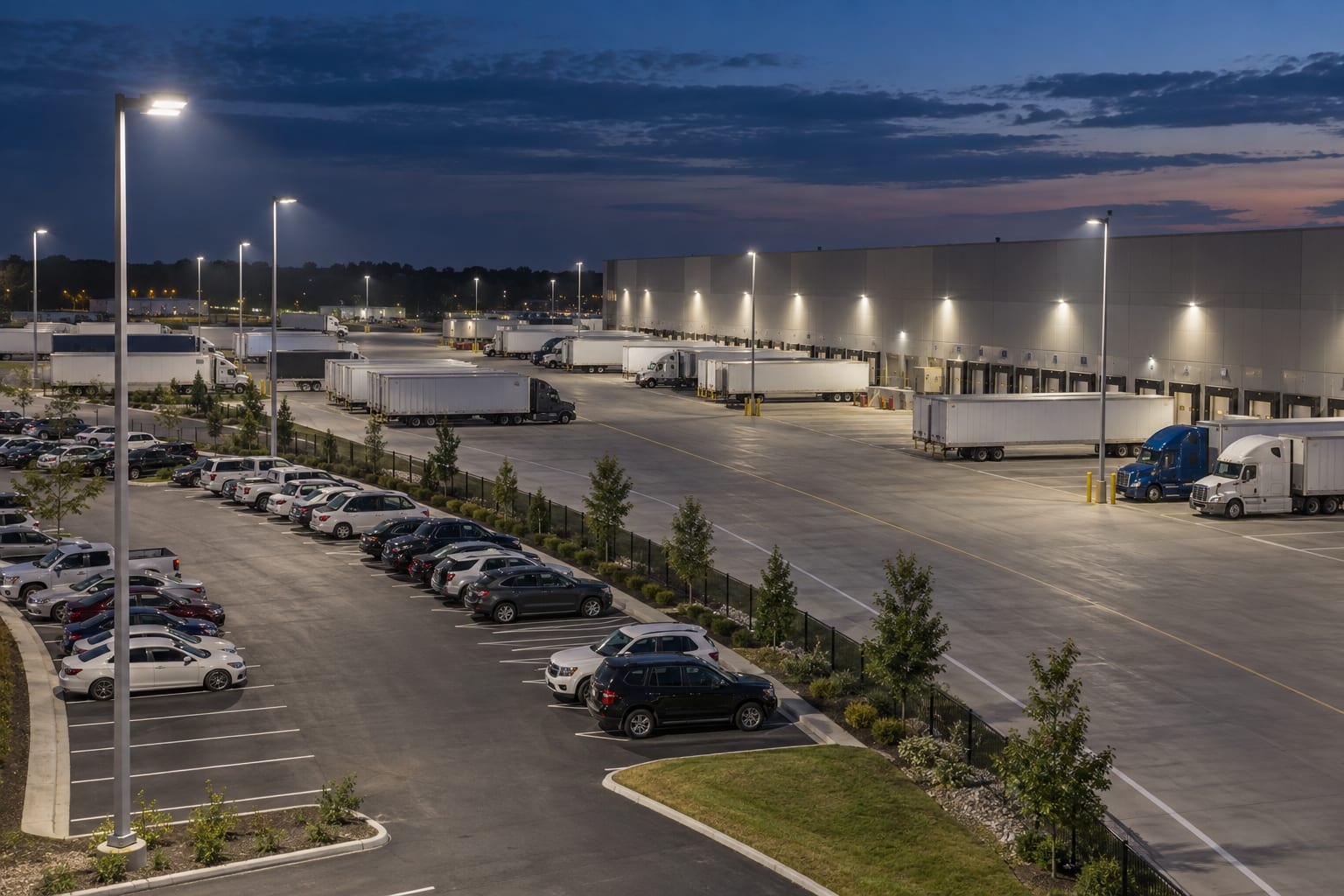
Truck staging, loading aprons and employee parking use different vehicle envelopes and operating patterns. Map trailer movements, dock approaches, queuing and pedestrian routes. Keep poles, barriers and maintenance equipment outside swept paths and working zones. A layout suitable for passenger cars should not be extended into a logistics yard without review.
Large open areas may justify different pole heights or head arrangements, but those options still require photometric, structural, foundation and operational comparison. Coordinate warehouse lighting and dock canopies to avoid severe transitions or shadows. Use controlled type marks where parking and yard zones meet.
Check delivery path, unloading area, crane position, overhead hazards and temporary traffic control before erection. Long shafts need a clear route to the foundation. Segment joints, if used, require defined engagement, orientation and assembly procedures. Do not plan a lift through active public areas without an agreed exclusion method.
For ongoing service, identify the access vehicle or equipment, its standing area and required clearances. Check whether parked cars, islands, canopies or trees block it. Keep approved fixture, bracket and load information in the asset record so replacements can be reviewed before installation.
Compare lighting performance, pole quantity, foundations, cable routes, structural demand, equipment access, boundary effects and construction phasing on the same basis. A layout with fewer poles may use different fixtures, larger foundations or more complex maintenance. A denser layout may create other civil and operational impacts.
Project economics depend on local equipment, labor, civil work, freight, energy rates, operating hours and risk allocation. Do not publish fixed percentage savings for pole quantity, cable or maintenance without a defined comparison. Document the assumptions and quantities used for the actual property instead.
A useful review places the calculation plan beside pole elevations and the luminaire data. Confirm that type marks, coordinates, mounting heights, head directions, optics and output settings agree. Check entrances, crossings, accessible routes, dark gaps, bright spots and boundaries rather than relying only on the summary table.
Resolve comments through controlled revisions. If a pole moves, update lighting, civil and electrical information together. If a fixture changes, update photometrics and equipment loads. This prevents an approved calculation from describing a system that the shop drawings and foundations cannot deliver.
Surface reflectance influences the calculated result and the driver's view. New concrete, aged asphalt, seal coating and painted markings do not behave identically. Use project-appropriate surface assumptions and record them with the model. If material selections change, review whether the calculation remains representative rather than retaining an undocumented default.
Rain, wet pavement, snow or dust can change apparent brightness, reflections and markings. The governing criteria determine what must be assessed, but the layout team should at least identify recurring environmental conditions. Avoid aiming high-intensity light toward approaching drivers where a wet surface or glossy façade can create a distracting reflection. Drainage design must also keep standing water away from bases and access points.
Controls can create different operating scenes for opening hours, low-activity periods, cleaning or emergency use. Define groups by functional zone and verify that reduced-output scenes still follow the owner's safety and operational requirements. A control schedule should not switch off alternate poles by convenience if that creates isolated dark areas or abrupt transitions.
Record drivers, sensors, communication equipment and control enclosures that affect the pole or wiring. Their mass, projected area, mounting and service needs belong in the equipment schedule when attached to the shaft. Coordinate circuiting with the civil cable route and identification marks so commissioning teams can test the same zones shown in the lighting model.
A solar assembly adds a module, battery arrangement, controller and associated mass and projected area. These components change orientation, shading, structural demand and maintenance access. Do not add a solar panel to a conventional parking pole drawing without repeating the energy, lighting, structural and foundation reviews for the complete assembly.
Assess solar resource, shading through the year, required operating profile, autonomy basis and component access using project data. The pole must support the defined module orientation and luminaire position while remaining clear of vehicles and trees. Where grid and solar options are compared, keep lighting criteria and operating assumptions visible so the result is not reduced to a fixture label.
A replacement project should survey actual pole coordinates, mounting heights, head directions, arms, bases, bolt patterns, doors, wiring and surrounding obstructions. Nominal asset records may not match field conditions. Photograph and measure a representative set, then identify variations rather than assuming every existing pole is identical.
Changing only the luminaire can alter distribution, tilt, projected area, mass and electrical demand. Recalculate the parking area with the proposed fixture and review the existing structure and foundation through the responsible process. Physical fit on an old tenon does not demonstrate optical performance or structural suitability. The general pole sourcing guide provides a broader document and change-control framework.
The pole general arrangement should state shaft geometry, material, openings, bracket, fixture interface, base plate, anchor pattern, finish and type mark. The site plan should show the same type, coordinate and orientation. Foundation and conduit drawings must use the released base information, not an earlier tender sketch.
Hold points should close changes that affect concrete, anchors, optics or loads before fabrication and construction continue. The street light pole shop drawing checklist helps reviewers connect equipment, geometry, structural data, civil interfaces and revisions. Remove superseded drawings from active field packs after approval.
Before lifting, confirm pole marks, bracket assemblies, fixture models and foundation readiness. Check anchor projection, conduit position, bearing or leveling detail and door direction. During erection, protect finishes and use approved lifting points. After positioning, verify plumb, bracket direction and fixture tilt against the released arrangement.
Do not correct misalignment through uncontrolled drilling, cutting, shimming or arm bending. Record the condition and obtain an approved response. Use the approved installation method statement for receiving, erection and handover, adapted to the site's safety and construction plan.
Commissioning should confirm fixture type, optic, output setting, tilt, orientation and control grouping. Check that landscaping, canopies or field changes have not blocked critical directions. Where measurements are required, use the specified method, calibrated equipment, agreed grid and suitable operating conditions rather than informal spot readings.
Resolve differences by tracing the installed system back to the model and drawings. A low value may result from orientation, setting, obstruction or coordinate changes, not automatically from insufficient wattage. Record final settings and approved changes in the handover package so maintenance personnel do not unknowingly alter the photometric basis later.
Once the parking lot light pole layout is defined, procurement can move to the galvanized parking lot light pole product page with a clear schedule. The main steel lighting pole manufacturer page connects the wider product family. These commercial pages should receive qualified inquiries rather than forcing this FAQ to duplicate full product specifications.
Nominal-height pages such as the 8m galvanized pole and 10m double-arm pole can help organize a schedule after photometric selection. Their names do not fix wall thickness, bracket loads, wind basis, plate or anchors. Use the dedicated mounting-height guide when the unresolved question is how height should be selected.
| Input | What to provide | Decision supported |
|---|---|---|
| Site | Current plan, zones, levels, coordinates, islands and obstructions | Pole placement |
| Lighting | Criteria, photometric file, output, optic, tilt and height | Layout and head arrangement |
| Structure | Wind basis, terrain, topography, every head and accessory | Shaft, bracket and reactions |
| Civil | Foundation concept, soil context, conduit and finished level | Base interface |
| Environment | Exposure, salts, contaminants, finish color and repair needs | Material and coating |
| Commercial | Quantities, type schedule, destination, packing and submittals | Proposal scope |
Before handover, reconcile installed pole marks, fixture settings, controls and approved field changes with the asset register. Clear final records allow future maintenance teams to evaluate replacements without rebuilding the original design basis from incomplete site observations.
Select it from the site geometry, photometric model, optic, spacing, glare, structure and service method.
Use the calculation for the actual fixture and layout; no universal spacing ratio applies.
Compare both for lighting, boundaries, vehicle protection, civil work and maintenance.
Keep poles out of vehicle paths and use a properly designed protected location.
No. Use photometric distribution, output, mounting height, tilt and site geometry.
Yes, when all heads, brackets, directions and loads are included in the design.
Use coordinated islands, curbs or barriers outside vehicle swept paths.
Yes. Model mature canopies and coordinate roots, irrigation and maintenance clearance.
The responsible civil designer uses pole reactions with site-specific ground conditions.
Send the site plan, fixture data, design basis, exposure, base concept and quantities.
Provide the current parking layout, pole coordinates, mounting-height reference, luminaire file and physical data, lighting criteria, wind basis, exposure, foundation concept, quantities and destination. Jieyao can organize the steel pole configuration and open interfaces for review.
Discuss Your Parking Lot Pole LayoutContact Us
Get a custom lighting solution and quotation for your project. Outdoor lighting manufacturer in Yangzhou, ChinaAbout Jieyao LightingYangzhou Jieyao Lighting Equipment Co., Ltd. is an outdoor lighting manufacturer focused on solar street light systems and high mas... Do you have any questions or requests?
Email: jay@jieyaolighting.com

Click to Chat.
Im online now.
Hey, I'm Xu Jie from Jieyao Lighting. What can I do for you? Welcome to contact me, WhatsApp: +86 13815843784
WhatsApp Us
🟢 Online | Privacy policy