

A roadway lighting pole cannot be selected from mounting height alone. A useful wind-load request identifies the governing design basis and site, the pole and arm geometry, every attached luminaire or other device, each device's mass and wind-facing data, and the base/foundation interface. The structural designer then evaluates the complete assembly under the applicable project rules. An equipment schedule that lists only “LED light, 150 W” does not define the projected-area or weight inputs needed for that review.
The checklist below helps a purchaser hand over data and responsibility. It is not a pole-capacity table, a stamped structural calculation, or a universal wind-speed recommendation. The authority having jurisdiction and project engineer choose the governing code, wind parameters, load combinations and any fatigue or dynamic checks. Ask for a calculation tied to the actual arrangement being bought.
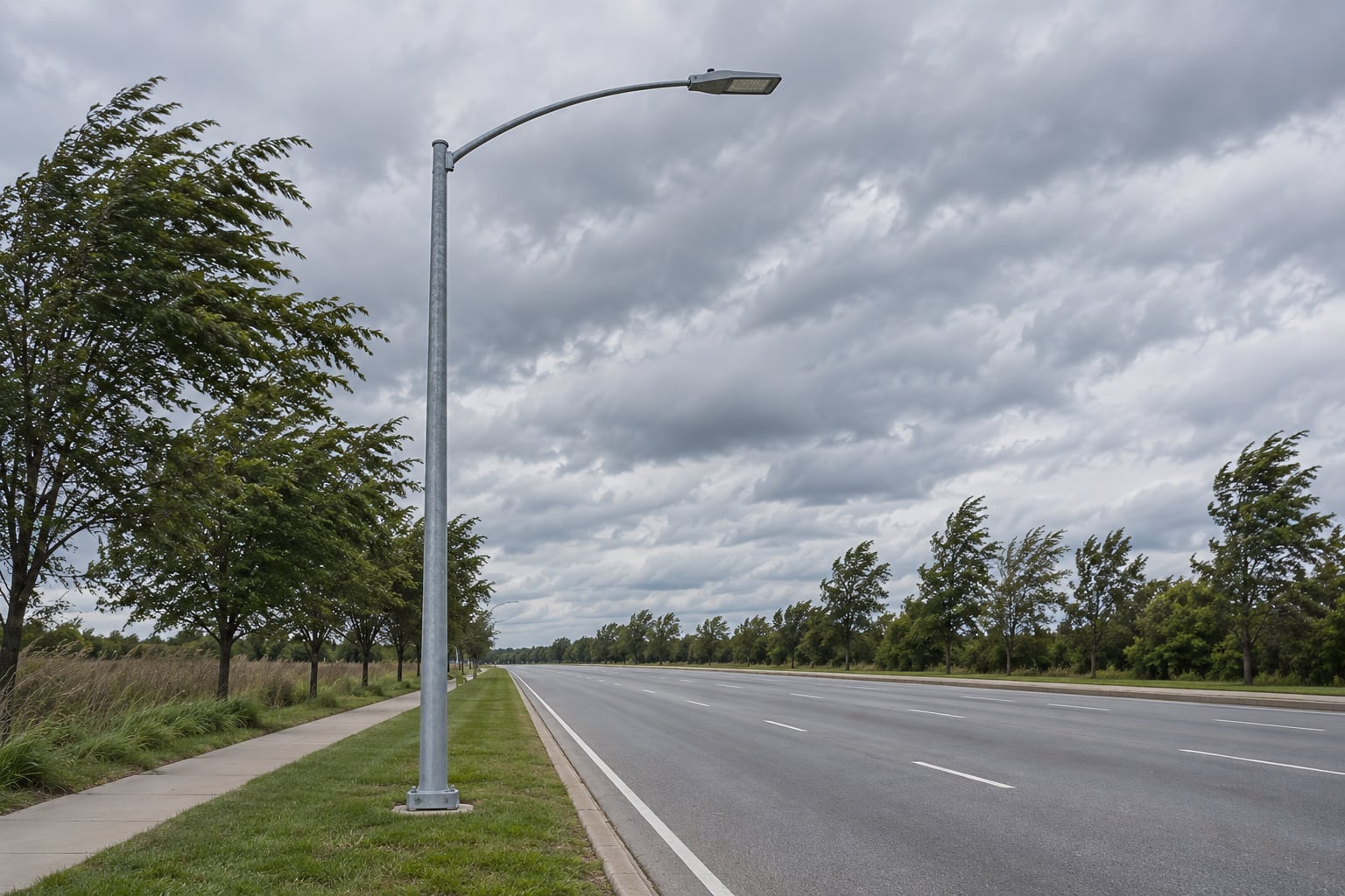
Start with the project location, road context, required service and governing edition of the structural-support standard or other local design documents. Identify which party supplies the site wind map value, exposure or terrain category, topographic information and any project-specific return-period or importance choices. Do not ask the pole fabricator to guess these from a city name. If a tender specifies a preapproved design basis, send the signed document and its revision; if it does not, ask the project engineer to establish it before the RFQ becomes a fixed-price fabrication order.
Next, draw the pole location relative to the carriageway, median, sidewalk or barrier, and state the intended foundation type. A flanged base and a direct-burial shaft have different foundation and erection interfaces. Ground-level conditions do not replace the wind parameters, but they do affect the foundation designer's scope, access and constructability. The foundation and anchor-bolt guide addresses that civil coordination separately.
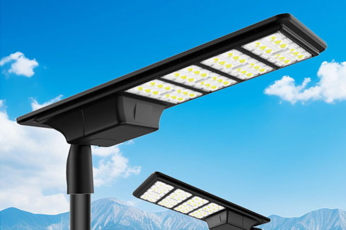
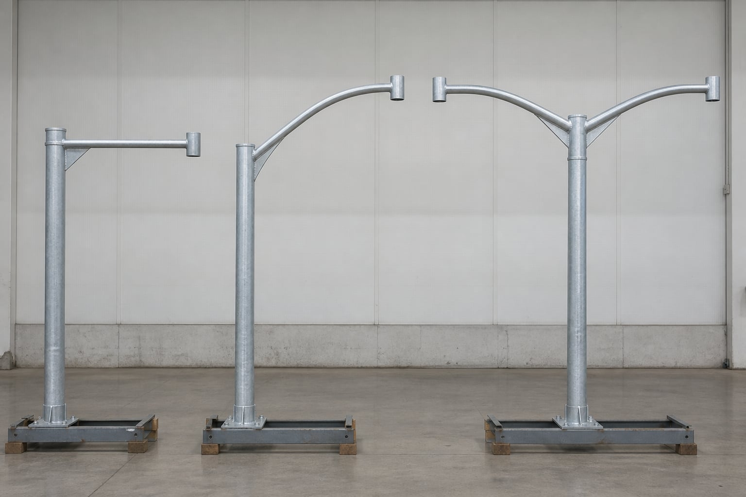
The luminaire's electrical wattage is not its aerodynamic description. Obtain the manufacturer data for the chosen model and orientation: effective projected area (EPA) or the equivalent inputs required by the governing method, mass, mounting interface, tilt/rotation and bracket details. Use the actual arm reach and rise, including any offset from the pole centerline. For twin arms, list each luminaire and its position. For future cameras, signs, banners or sensors, state whether they are included in this design, explicitly excluded or reserved as a quantified future allowance; “smart-ready” is not a load case.
This table is a purchaser handoff checklist. The calculation method and acceptance values belong in the approved engineering package, not in a generic website article.
| Input group | Data to obtain and identify by revision | Typical source / owner |
|---|---|---|
| Governing basis | Jurisdiction, applicable structural-support documents, project wind and load criteria | Owner / engineer of record |
| Site and exposure | Pole coordinates, road/terrain context, topographic information where relevant | Survey / civil engineer |
| Pole geometry | Mounting height, shaft profile, wall/material proposal, door location, base type | Lighting design and pole supplier, coordinated by engineer |
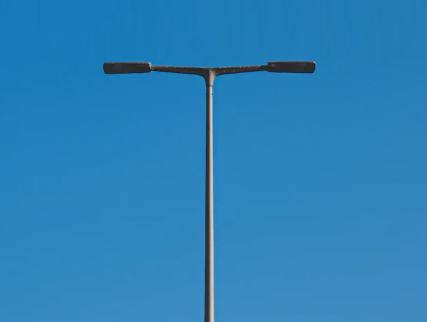
| Arm geometry | Single/twin configuration, reach, rise, orientation, connection and attachment elevations | Lighting layout and approved shop drawing |
| Luminaire data | Exact model, quantity, mass, EPA or equivalent required shape data, mounting/tilt | Luminaire manufacturer and lighting designer |
| Other attachments | Each camera, sign, sensor or reserve allowance with position, mass and wind data | Equipment owner / future-use sponsor |
| Civil interface | Base-plate and anchor geometry or embedment concept, conduit and foundation responsibility | Structural and civil designers |
| Evidence | Calculation revision, drawings, equipment schedule and approved substitutions | Engineer / buyer document control |
An incomplete value should be marked open, not silently treated as zero. The supplier can price alternative geometries provisionally, but the final shaft, arm, weld, base and anchor arrangement must be checked against one controlled set of inputs. The pole arm and luminaire interface guide covers mechanical fit and routing; this page owns the wind/EPA input collection.
Changing arm reach changes the location of the luminaire load relative to the shaft. Changing a luminaire changes both its mass and wind-facing behavior; the two should not be conflated. A camera bracket or sensor can add projected area at a different elevation and orientation. The designer also has to consider whether a sign panel, banner or future device is actually authorized for the pole. Avoid copying the capacity of a visually similar pole or a previous project with a different luminaire schedule.
The shop drawing should show the equipment envelope, bolt/slip-fit dimensions, bracket orientation and cable entry, with device IDs that match the structural input list. If the luminaire is substituted after approval, the replacement must be compared on the data actually used in the analysis, not just on wattage or appearance. Keep the approved drawing revision paired with the calculation revision; the shop drawing checklist describes the wider approval package.

The second table is a re-review trigger, not another RFQ input list. It tells project participants when to stop treating the old calculation as the current one.
| Proposed change after design release | Why the old design may no longer represent the order | Record to revise before fabrication or installation |
|---|---|---|
| Luminaire model or quantity changes | Mass, EPA, mounting geometry and attachment elevation may differ | Device schedule and engineer's comparison/calculation |
| Arm reach, rise or orientation changes | Load location and connection demand change | Pole/arm shop drawing and structural check |
| Camera, sign or sensor added | New wind-facing area, mass, cable route and service access | Approved attachment schedule, bracket and structural review |
| Base, anchor or foundation geometry changes | Load transfer and fit may change even if the shaft is unchanged | Pole-base drawing and civil/structural coordination |
| Site or design-basis revision changes | Governing wind/exposure or acceptance basis may change | Revised site criteria and signed design record |
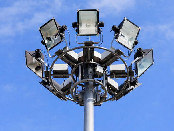
If the project includes a high mast with a large luminaire headframe and lowering system, use a design package specific to that system; the high-mast wind-load and EPA guide owns that different search intent. A traffic signal mast arm also has a different equipment arrangement and fatigue sensitivity. This checklist is for conventional roadway lighting poles.
The pole supplier should issue the reactions or other foundation interface information required by the engineer, together with the base-plate and anchor arrangement. The civil designer must confirm that the foundation, anchors, concrete and soil assumptions suit the site. A pole drawing with a bolt circle but no agreed design reactions is not a complete handoff; likewise a foundation drawing using a different bolt circle cannot be released by assumption. Document who owns anchor supply, templates and final survey. A field-installed pole should be checked against the approved drawing, not the hero photo on a product page.

Send the site/design-basis document, lighting layout, pole schedule, arm arrangement, complete equipment list with mass and EPA data, attachment drawings, foundation/interface constraints, corrosion environment, document deliverables and approval roles. Ask the bidder to identify assumptions and exclusions in a comparison sheet. Where the luminaire model is still open, request a defined design envelope and a revision process, not an unqualified promise that any luminaire will fit. Contact Jieyao with these controlled inputs for a project-specific pole proposal; any final structural capacity remains subject to the agreed engineering package.
No. Wattage describes electrical demand, not device mass or wind-facing area. The equipment manufacturer and governing design method determine the required aerodynamic input.
Not without comparison. Check the replacement's declared data, orientation, quantity and mounting location against the approved calculation and drawing.
The same categories of information apply, but each arm and luminaire needs its own geometry and equipment data. A twin arrangement is not simply a title change.
The owner and project engineer should identify the governing standard and site parameters. A supplier should not silently invent them from an address or reuse an unrelated project value.
State a quantified allowance and the intended mounting positions for engineering review, or say that future devices are excluded and will need a new check. The word “future-ready” alone is not an input.
Contact Us
Get a custom lighting solution and quotation for your project. Outdoor lighting manufacturer in Yangzhou, ChinaAbout Jieyao LightingYangzhou Jieyao Lighting Equipment Co., Ltd. is an outdoor lighting manufacturer focused on solar street light systems and high mas... Do you have any questions or requests?
Email: jay@jieyaolighting.com

Click to Chat.
Im online now.