
Before reviewing values, locate the governing lighting standard and edition, the road or area class, the maintenance basis and the performance criteria in the tender. Identify which segment is being assessed and where the calculation begins and ends. A road section, intersection, pedestrian crossing and parking facility may be governed by different design tasks. This guide focuses on road corridors and does not duplicate parking-lot luminaire-layout guidance.
Also check the revision of the drawings and the calculation report. A photometric plan tied to an earlier road layout can appear complete while omitting a changed lane, median, barrier or luminaire location.

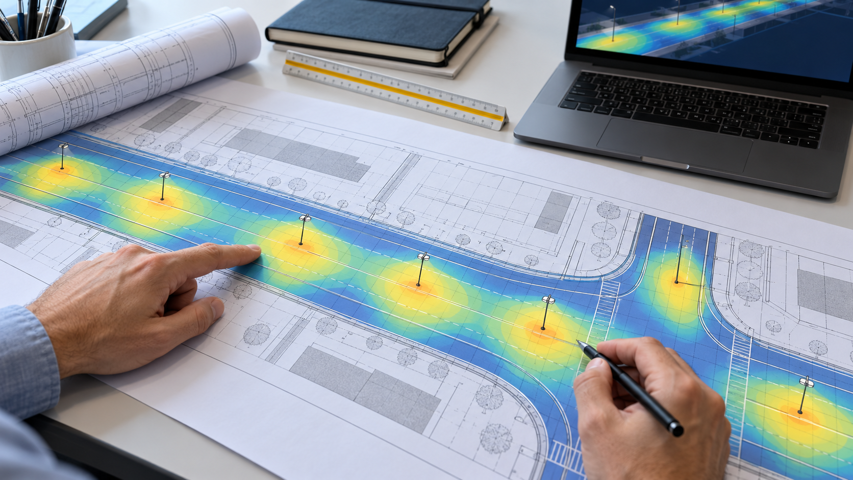
Photometric-plan review concept; the color pattern is illustrative, not a measured result.
| Check | What to inspect | Common review action |
|---|---|---|
| Road geometry | Lanes, width, curvature, median, grade, sidewalks and obstructions match the current drawing. | Request a revised calculation if the model omits a defined area or uses a superseded plan. |
| Calculation grid | Grid spacing, points, boundaries and evaluation zones follow the specification. | Confirm the designer's method when the tender is silent or ambiguous. |
| Surface and maintenance assumptions | Road-surface classification/reflectance and maintenance factor are documented as required. | Check the basis and source; do not substitute a generic assumption. |
| Luminaire input | IES/LDT photometric file, output setting, optic, tilt and mounting height match the offered model. | Re-run the model if a different file or configuration is submitted. |
| Adjacent boundaries | Relevant sidewalks, property boundaries, transitions and conflict areas are shown when required. | Extend or split the model to match project acceptance scope. |
Uniformity is not a standalone pass/fail number detached from the design brief. Reports commonly show average and minimum levels and one or more ratios, but the exact metrics and limits are chosen by the governing standard and project specification. Confirm whether the report uses maintained or initial values and whether the ratio is defined as minimum-to-average, minimum-to-maximum or another stated method. Never compare ratios until the definitions match.
Look for local dark areas near the road edge, between poles, at curves or where a median interrupts the pattern. A high average can coexist with a low minimum or an uneven transition. Conversely, a single ratio may not describe the full visual task. Review the point grid, surface assumptions and rendered contour as evidence—not as a substitute for the tabulated results.
Does the reported average use the intended area and maintained basis stated by the project?
Where does the lowest point occur, and is that location part of the required grid?
Are the ratio definition and glare metric the ones named in the adopted criteria?
When a calculation misses criteria, do not immediately raise wattage. First verify that the correct photometric file, output setting, mounting position and tilt were modeled. Then inspect grid density, road-surface inputs and calculation boundaries. If those are valid, the designer can test an alternative optical distribution, spacing or mounting arrangement and recalculate. Any change should be tracked to the drawing revision and model schedule.
Check transitions between adjacent sections as well as the nominally compliant segment. FHWA's roadway-lighting reference notes that uniformity and glare should be considered with illumination levels and that geometry, height, luminaire type and placement affect the result. Final acceptance thresholds remain those specified by the authority.
| Handover item | Purpose |
|---|---|
| Calculation report and file version | Records the design revision and evaluation area. |
| Photometric file/model schedule | Connects the calculation to the exact proposed luminaire configuration. |
| Assumptions register | Documents grid, surface, maintenance, tilt, output and control inputs. |
| Criteria comparison | Shows each required metric and result using the same definitions. |
| Open items and deviations | Prevents unresolved exceptions from being mistaken for approval. |
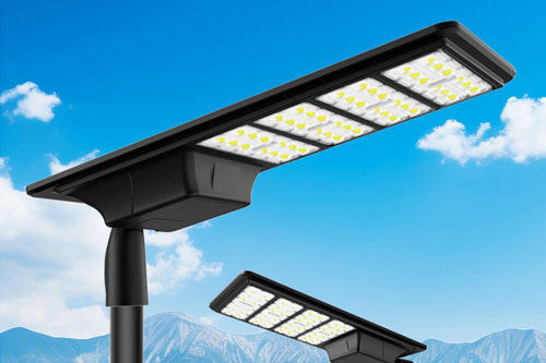
Jieyao's LED street-light product page provides a product-family starting point. For procurement review, request the exact configuration and matching photometric file; a general brochure image is not enough to validate a design calculation.
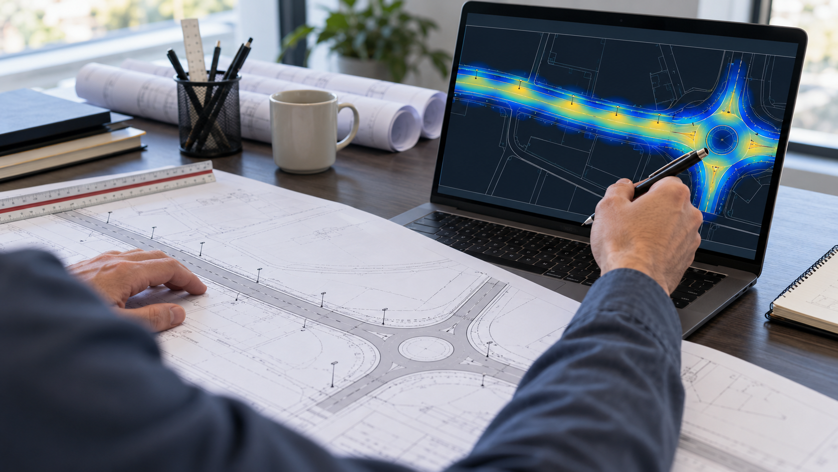
Plan-review workflow context; the displayed heat map is not a calculation for a Jieyao product.
| Red flag | Why it matters | Review question |
|---|---|---|
| Product schedule and report names do not match | The modeled photometry may not represent the offered configuration. | Which model, optic, output setting and file generated the result? |
| Average is shown without minimum or ratio | Non-uniform sections can be hidden by an area-wide average. | Which uniformity metrics are required and what are their definitions? |
| Maintenance factor is unexplained | Initial and maintained results are not directly comparable. | What factor and maintenance assumptions are specified? |
| Grid stops before a curve or crossing | The omitted transition or conflict area may be part of the acceptance scope. | Does the calculation boundary follow the tender drawings? |
| Drawing revision is missing | Geometry and luminaire positions may be stale. | Which signed drawing revision was modeled? |
When requesting a revision, list the exact input to change and the criteria to retain. A useful comment identifies a drawing coordinate, calculation zone or model designation rather than saying only “improve uniformity.” Ask the designer to return the revised report, the updated luminaire schedule and a change summary. If a deviation remains, record the value, definition, location and approving party in the review log. This makes the final design traceable from tender to procurement and handover.
Every comment should identify the report, page or calculation zone it refers to, the criterion being checked and the evidence needed to close it. When a revised run arrives, compare its inputs with the last accepted version and verify that only the intended change was made. If the roadway geometry, maintenance basis or photometric file changed too, treat the submission as a new comparison rather than a direct before-and-after result.
Keep a revision log that links the calculation, drawing, luminaire schedule and response to comments. Assign unresolved issues to the authority, designer, contractor or supplier instead of leaving them as ambiguous notes. This is especially helpful where a report includes several road segments or alternate fixture configurations.
At handover, preserve the calculation file and its source photometric files with the as-supplied product schedule and control settings. That record does not replace field commissioning or any required measurement; it gives the asset owner a traceable reference for maintenance, fault investigation and future design changes.
Uniformity figures are useful only when the reviewer knows how they were calculated and which grid produced them. A report may include minimum-to-average or minimum-to-maximum ratios, but the name, direction and evaluation area must match the project's standard. Do not compare a value from one calculation plane or grid with a value from another and call the larger result “better.” First verify the definitions, included points, boundary treatment and reporting precision.
Read the minimum alongside the average and maximum rather than in isolation. An acceptable average can mask a local dark patch, while one high point can distort a ratio without describing the corridor as a whole. Review the contour plot and point-by-point output to locate unusual peaks, gaps, abrupt transitions or edge effects. Then connect each observation to the corresponding layout element—spacing, optic, aiming, mounting height, road width or obstruction—before requesting a design revision.
Review comments should identify the drawing revision, calculation file, disputed area, criterion and requested evidence. “Uniformity looks poor” is difficult to action; a precise note might ask the designer to identify the lowest calculation points, confirm the grid boundary and resubmit the ratio using the specified definition. The reviewer should avoid prescribing a different luminaire or spacing before the design team has diagnosed the input or modeling issue.
When a revised report arrives, compare it with the previous version. Confirm that changed photometric files, output settings, tilt, mounting locations or road-surface assumptions are listed, and review the affected outputs again. If a change was made to fix one dark area, check that it did not create excessive brightness, glare, spill or a new discontinuity elsewhere. This closes the loop between a comment, the design response and the acceptance record.
| Review finding | Possible input to verify | Useful follow-up |
|---|---|---|
| Unexpected low point | Grid boundary, spacing, tilt, optic or local obstruction. | Request point coordinates and a revised contour plot. |
| High peak near a pole | Output setting, overlap, calculation point placement. | Check both local value and surrounding distribution. |
| Ratios differ between reports | Metric definition, plane, grid and included points. | Recalculate both versions on the same approved basis. |
| Revision cannot be reproduced | File identity, software inputs and drawing revision. | Ask for a complete input schedule and version record. |
A review can fail even when the calculation software is used correctly if the model file and equipment schedule describe different configurations. Check the exact photometric file name and revision, the selected output setting, optic, tilt and mounting height against the supplier’s schedule. Confirm that any control level used in the calculation is available in the offered configuration and that the calculation’s maintenance basis is documented as the project requires.
When a change is approved, update the calculation, drawing, schedule and deviation log together. Mark superseded files clearly and state which revision governs procurement. This avoids a common handover problem: an apparently compliant report that refers to a luminaire or road geometry no longer included in the construction package.
The reviewer’s role is to identify whether the submitted evidence answers the specified question and to record unresolved assumptions. Design approval remains with the appointed lighting professional and project authority. A transparent review trail is more useful than an isolated pass/fail label because it shows what was assessed, on what basis and against which revision.
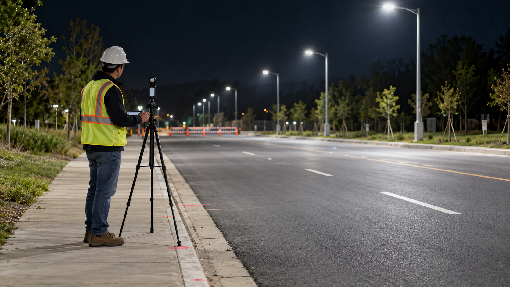
Field-check context; any measurements must follow the project's approved method and operating conditions.
Not necessarily. The project may also require minimum values, uniformity ratios, glare limits, adjacent-area checks or maintained values. Review the complete criteria schedule.
Ask the designer or authority to state the formula and evaluation area before comparing results.
First validate the input file, output setting, layout, tilt, grid and surface assumptions. A different distribution or arrangement may address the cause more directly.
This article is limited to roadway calculations. Parking facilities have their own layouts and criteria; review them under the applicable parking-lighting standard.
No. The plan image is illustrative. Use signed project calculation files and the exact model photometry for decisions.
Contact Us
Get a custom lighting solution and quotation for your project. Yangzhou Jieyao Lighting Equipment Co., Ltd. manufactures outdoor lighting and steel poles in Guoji Town Industrial Park, Gaoyou City, Yangzhou, Jiangsu, China. The company reports a 10,000 m² factory site, more than 60 employees including more than 10 technical personnel, and more than 100 production and testing machines. The present company name dates from 2017; Jieyao Poles’ published history traces the team’s manufacturing lineage to 2006. The stated 15 years of experience refers to the team. The company reports exports to more than 60 countries. Do you have any questions or requests?
Email: jay@jieyaolighting.com

Click to Chat.
Im online now.
 English
 Español
 Bahasa Indonesia