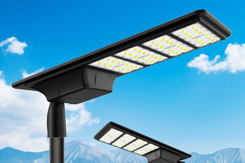

These terms describe related but different effects. Spill light falls outside the intended area; glare is a bright source or excessive luminance that can cause discomfort or impair visibility; sky glow is upward light scattered in the atmosphere. One fixture adjustment may affect more than one effect, so the review should name the problem being solved.
FHWA's roadway-lighting handbook notes that the impact on the environment and nearby properties should be considered in road design. It also cautions that reducing or eliminating trespass should not take precedence over adequate roadway lighting. That principle matters: a mitigation plan needs to protect the road user's visual task and the receptor at the same time.
| Issue | Where to inspect | Possible design levers to test |
|---|---|---|
| Spill beyond the road | Property line, windows, upper floors, gardens and other boundaries named in the criteria. | Distribution, luminaire orientation, mounting position, output setting and shielding where supported by the product. |
| Glare to drivers or residents | Approach views, sight lines, receptor viewpoints and source visibility. | Aiming, mounting geometry, optics and layout changes, with roadway criteria rechecked. |
| Sky glow | Upward light from the installation and reflected light from surfaces. | Optics, tilt, output scheduling and material reflectance assumptions where applicable. |

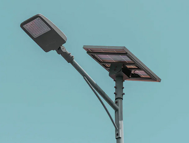
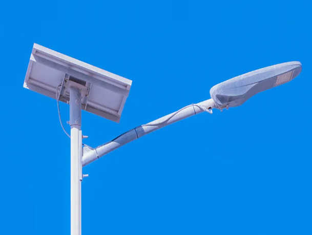
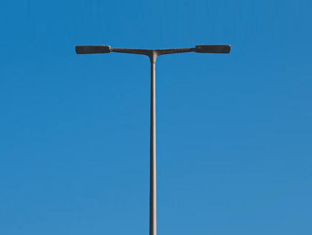
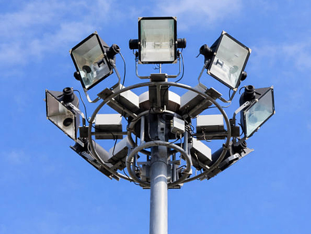
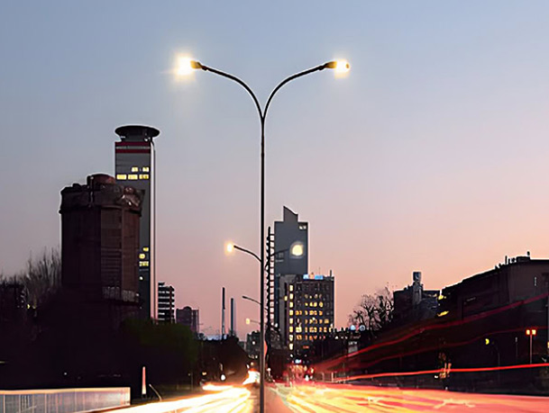
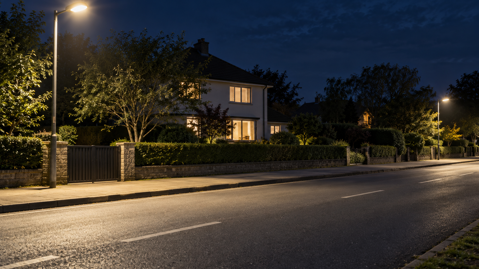
Residential-road context for spill review; no measured boundary value is represented.
Mark nearby homes, windows, hospitals, schools, ecological areas or other sensitive locations identified by the project. Record elevations and viewing directions where they affect the assessment. Confirm whether the specification asks for evaluation at the property boundary, a facade, a window plane or another receptor plane; the answer depends on local requirements and the scope.
Capture the road geometry and the context: carriageway edge, sidewalks, barriers, trees, signs, existing luminaires and proposed pole locations. Record the operating schedule and any curfew or dimming requirements in the tender. Without these details, a plan may report spill for the wrong boundary or the wrong output state.
Check the exact photometric file, output setting, mounting height, tilt and calculation grid. Confirm the model matches the tendered fixture.
Compare distributions, aiming, mounting positions or shielding options that the selected product actually supports. Re-run roadway and receptor checks together.
If dimming or time scheduling is proposed, show the operating states and confirm that each state meets the applicable design requirement.
Do not assume that a nominal “full cut-off” description, a lower wattage or a shield guarantees acceptable spill. The result depends on the exact photometry, tilt, position, surface, boundary and calculation assumptions. Ask the designer for a model-specific comparison of the original and revised layouts.
| Evidence | What it should show |
|---|---|
| Site and receptor plan | Road edge, properties, sensitive locations, calculation planes and luminaire positions. |
| Exact luminaire data | Model/configuration, photometric file, output setting, tilt and mounting details. |
| Calculation results | Boundary/receptor results and roadway results on a consistent, stated basis. |
| Operating schedule | Normal, reduced-output and any curfew states that are part of the proposal. |
| Mitigation record | Before/after inputs, deviations and confirmation that road criteria remain satisfied. |
Jieyao Lighting supplies roadway LED luminaires and lighting poles. For a road next to homes, provide the receptor map and required boundary criteria along with the road design brief. A project review can then identify which product photometry and mounting details need to be checked. This article does not claim a measured residential installation or guarantee compliance without a project calculation.
See the LED street-light product family for roadway fixtures. Ask for model-specific photometric files and supporting documents through the Jieyao contact page.
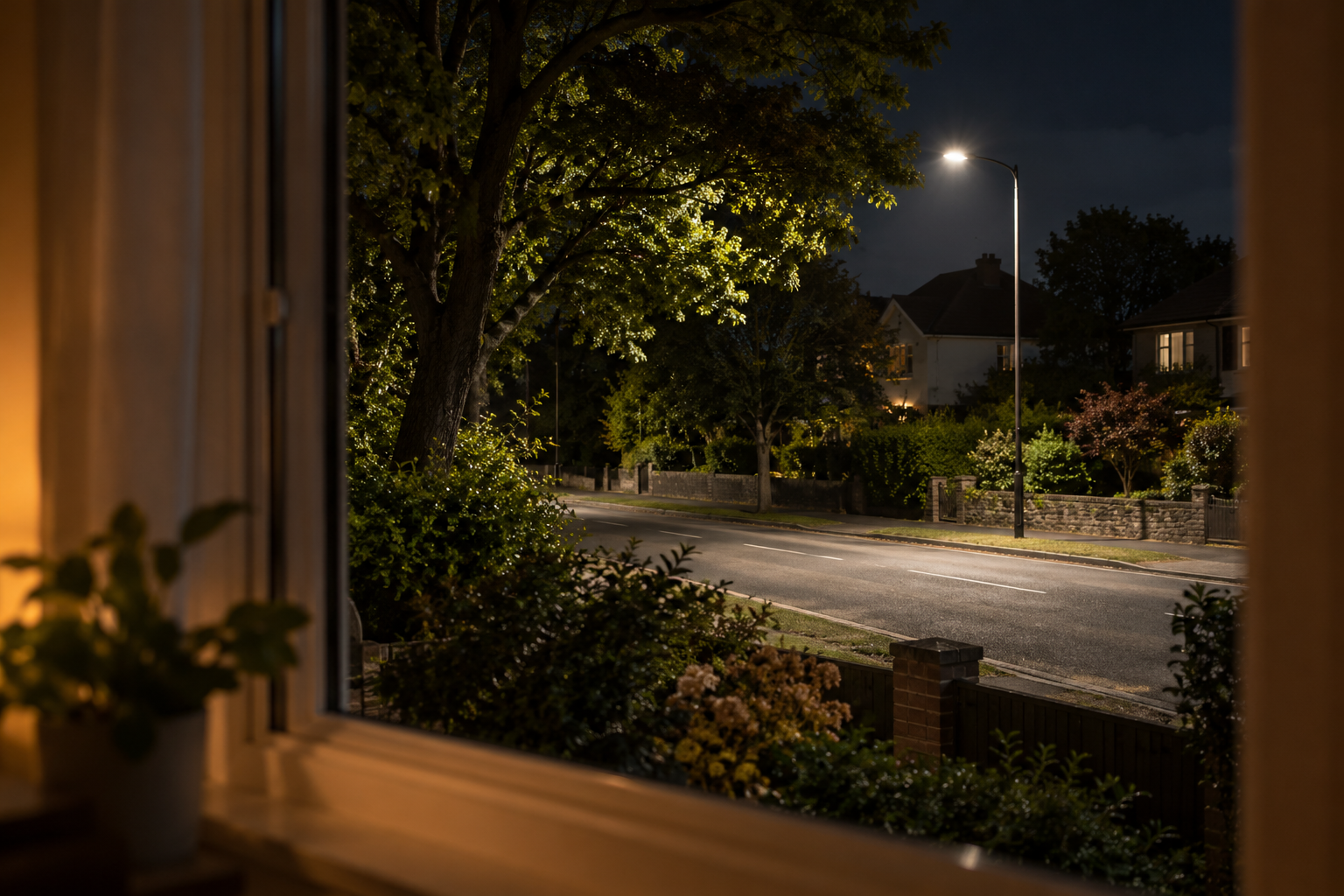
Residential receptor viewpoint for spill review; this scene represents context, not a measured boundary result.
A before-and-after comparison should use the same receptor locations, calculation planes, operating state and roadway criteria. If the boundary, output or maintenance basis changes between runs, the comparison may be misleading. Keep both the road results and the receptor results visible, and note any place where a mitigation option moves light rather than reducing it.
| Option to test | Potential benefit | Trade-off to review |
|---|---|---|
| Alternative distribution | May place more light within the intended roadway area. | Recalculate the carriageway, boundary and glare metrics using the exact optic. |
| Re-aim or reposition | Can change the direction and location of spill. | May affect uniformity, visibility, clearances or maintenance access. |
| Output scheduling | Can reduce output during an approved operating state. | Confirm the control logic and verify roadway criteria in every state. |
| Shield or accessory | May limit light in a particular direction if the model supports it. | Check fit, thermal/electrical instructions and updated photometry. |
Keep a receptor map, approved luminaire schedule, calculation inputs, operating schedule and record of accepted deviations together. If a resident complaint arrives after installation, these documents help distinguish a design issue from a changed setting, replacement product, damaged optic or new obstruction. Field checks should be performed with appropriate calibrated equipment and a method accepted by the authority; a phone photograph alone cannot establish a numeric compliance result.
A post-installation complaint should be investigated against the approved design and the conditions at the time of observation. Record the luminaire identity, operating mode, nearby construction or vegetation changes, observer location and the time and weather conditions. Where a measurement is required, use the authority's defined method and instrument procedure; an informal phone photograph cannot establish a compliance result by itself.
Compare the installed optic, tilt, mounting position and controls settings with the accepted drawings and schedule. If they differ, determine whether the change was approved and whether the revised arrangement was recalculated. This separates a design issue from an installation or control-setting issue and points to the right corrective path.
Any mitigation should be checked both at the property boundary and on the road. Keep before-and-after calculations or measurements, the accepted operating schedule and the approval record together. A documented process helps the agency respond consistently without sacrificing roadway criteria to solve a separate boundary concern.
When a boundary result or resident concern triggers a review, begin with the verified inputs: exact luminaire photometry, mounting location, orientation, output state, calculation conditions and receptor position. Confirm that the model represents the installed or proposed arrangement before changing equipment. A wrong file or incorrect tilt can make a mitigation comparison misleading.
Then assess options in a sequence that preserves the road-lighting task. A different distribution, careful aiming, revised mounting position, shielding accessory or controlled output may each help in some circumstances, but none is universally suitable. After every change, rerun the roadway and boundary checks against the criteria that apply. Document any trade-off among road performance, visibility, glare, spill, energy use and maintenance so the decision is transparent to the authority and community.
A resident report is important evidence of experience, but it is not itself a photometric measurement. Record the location, time, operating state, view direction and whether trees, vehicles or temporary equipment changed the scene. A site visit may reveal an aiming shift, failed shield, changed control schedule or newly exposed window. Keep those observations separate from a calculation report, which depends on a defined model and assumptions.
If field measurements are requested, agree the instrument, calibration status, measurement points, background-light treatment and operating state before testing. Record weather and any temporary sources that could affect readings. The project authority should determine the evaluation method and applicable limits. A supplier can provide model data or evaluate a revised configuration, but should not declare legal compliance without the right project criteria and supporting evidence.
| Evidence type | What it can answer | What it cannot establish by itself |
|---|---|---|
| Resident observation | When, where and how light is experienced. | A standardized boundary value or legal breach. |
| Photometric calculation | Modeled results for defined files, geometry and assumptions. | The as-installed condition if the site differs from the model. |
| Field measurement | Measured conditions at agreed points and operating state. | Other locations or conditions not included in the test. |
| Installation record | Installed model, tilt, shield and control configuration. | Future conditions after vegetation or site changes. |
When a concern is reported, document the receiving window or outdoor area, the direction of view, the time and operating state, and whether the light is steady or intermittent. Note nearby sources such as road luminaires, signs, vehicle headlights and private lighting. A location plan and short description can prevent the review from starting with the wrong source or boundary.
Ask the designer or road operator to compare the approved design with the as-installed arrangement: luminaire model and optic, mounting orientation, tilt, shielding, control schedule and nearby obstructions. If a field measurement is commissioned, define the instrument, location, setup, background conditions and operating state in advance. Repeat observations should use a comparable method so that before-and-after results can be interpreted responsibly.
Possible changes should be screened for secondary effects. A shield, lower output setting or revised aiming may reduce light in one direction but also alter the roadway calculation, uniformity, visibility or maintenance requirements. The responsible designer should assess the complete task and retain the approved revision rather than making an undocumented field adjustment.
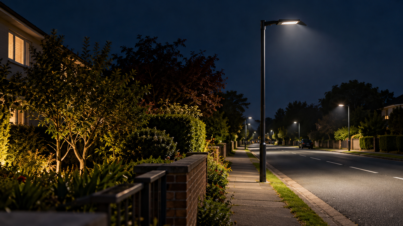
Aiming and shielding are options to evaluate alongside roadway criteria and the exact photometric file.
No. Spill describes light outside the intended area; glare concerns source brightness and visibility effects. A project may need to review both, plus sky glow.
No. Numeric limits and evaluation planes depend on the jurisdiction, environmental zone and adopted project documents. Use the criteria named by the authority.
Not necessarily. Distribution, position, tilt, shielding, output control and the road's required visibility all matter. Model and recalculate the complete scene.
Only if the authority and project design allow that operating state. Any dimmed or switched state should be reviewed against the applicable road criteria and control plan.
FHWA advises considering environmental and abutter impacts, while noting that minimizing trespass should not take precedence over adequate roadway lighting.
Use the currently adopted local requirements for numeric limits and acceptance decisions.
Contact Us
Get a custom lighting solution and quotation for your project. Yangzhou Jieyao Lighting Equipment Co., Ltd. manufactures outdoor lighting and steel poles in Guoji Town Industrial Park, Gaoyou City, Yangzhou, Jiangsu, China. The company reports a 10,000 m² factory site, more than 60 employees including more than 10 technical personnel, and more than 100 production and testing machines. The present company name dates from 2017; Jieyao Poles’ published history traces the team’s manufacturing lineage to 2006. The stated 15 years of experience refers to the team. The company reports exports to more than 60 countries. Do you have any questions or requests?
Email: jay@jieyaolighting.com

Click to Chat.
Im online now.
 English
 Español
 Bahasa Indonesia