


Configure a tapered octagonal lighting pole around the photometric layout, declared luminaire and arm loads, project wind basis, foundation interface, electrical access, galvanized finish and approved drawings.
An octagonal galvanized steel street light pole is a hollow tapered shaft formed with eight flat faces and eight longitudinal corners. The lower cross-section is normally larger than the upper cross-section, creating a controlled taper from the base toward the luminaire. Hot-dip galvanizing provides the primary steel-protection system, while the shaft geometry, wall schedule, openings, arm, base and anchors are developed for the declared project conditions.
The phrase “octagonal light pole” describes shape, not a complete specification. Two poles with the same nominal height can differ in top diameter, base dimension, plate thickness, steel grade, arm outreach, fixture area, wind basis and access arrangement. Jieyao therefore treats each pole mark as an engineered package. Buyers receive a proposal connected to the lighting layout and project inputs instead of an unsupported catalogue size.
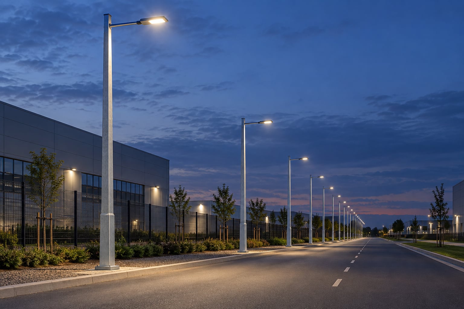
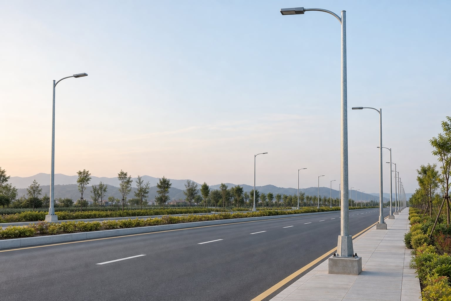
Tapered octagonal poles are widely considered for municipal roads, industrial access routes, logistics parks, residential streets, commercial developments, parking approaches, campuses and transport facilities. Their visible facets create a crisp contemporary profile and make orientation easy to show on drawings. Single-side arms can serve verge positions, twin arms can serve medians, and post-top arrangements can support selected area or pedestrian lighting layouts.
Application names do not determine a final pole. A sheltered campus road and an exposed port approach may use similar mounting heights but place very different demands on the structure and finish. Record the exact zone, pole setback, luminaire position, maintenance access, underground constraints and environmental exposure. If a development contains several road types, assign separate marks so each octagonal street light pole can be reviewed against its actual duty.
The eight flat faces make the shaft visibly different from a continuously round pole. They provide clear reference surfaces for dimensional checks and for orienting access doors, arms and identification marks. The folded corners are part of the structural section and must remain straight and consistent. Across a row of installed poles, controlled facet orientation contributes to an orderly appearance.
Eight sides do not create a universal strength advantage. Capacity depends on the complete section, material, taper, wall thickness, openings, welds and load direction. A properly designed round pole and a properly designed polygonal pole can both serve road lighting. The correct comparison uses project calculations, interface details, manufacturing availability and the visual intent rather than a slogan about one geometry being better.
An octagonal shaft has measurable dimensions across flats and across corners. A round tapered shaft has a continuous outside diameter. That difference influences base covers, access openings, decorative sleeves, clamps and replacement compatibility. It also changes how highlights appear along the shaft: facets create defined planes, while a round profile gives a continuous reflection.
Neither shape should be substituted after approval without checking the drawing and calculation basis. If the tender permits alternatives, each supplier should state the proposed cross-section and dimension convention. Buyers comparing a polygonal option with a round tapered galvanized steel light pole should align height reference, top load, wind inputs, base type, coating and documentation before comparing the commercial offer.
Compare geometry and interface records on a common project basis; neither profile has a universal capacity advantage.
| Review topic | Octagonal tapered shaft | Round tapered shaft |
|---|---|---|
| Dimension convention | Across flats, across corners and facet orientation | Outside diameter, roundness and taper |
| Access opening | Door face, corner clearance and local reinforcement | Door cutout, seam orientation and curved mating surface |
| Mating components | Faceted base cover, clamp or slip-joint geometry | Circular sleeve, cover, clamp or slip-joint geometry |
| Approval evidence | Actual section, load direction, connections and drawings | Actual section, load direction, connections and drawings |
A tapered octagonal pole reduces in cross-section toward the top, whereas a straight polygonal shaft maintains the same principal dimensions through its main length. The two are not interchangeable simply because both have flat faces. Taper influences visual proportion, section properties, forming, nesting, slip-joint design and the size of mating components.
A straight shaft may suit a particular architectural or equipment-mounting requirement. A tapered shaft often presents less visual mass near the luminaire while retaining a larger lower section for structural demand and service access. The selection should follow the approved engineering concept, availability and lifetime maintenance plan rather than an assumed default.
Mounting height is a photometric and civil coordination decision. It affects spacing, uniformity, glare, luminaire output, pole count, setback, visual scale and maintenance access. The lighting designer should model the proposed fixture and optic at the actual road width, surface, outreach, tilt and maintenance assumptions. A nominal pole height cannot replace that calculation.
Define whether a stated dimension means shaft length above the base, luminaire mounting height or overall height including arm rise. Show the reference in the schedule and elevation. For fixed-height enquiries, the 8m galvanized street light pole, 10m single-arm pole, 10m double-arm pole, 12m highway pole and 15m highway lighting pole pages organize height-specific procurement questions.
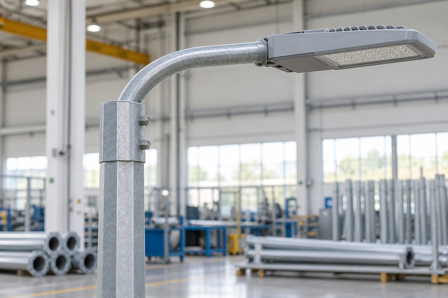
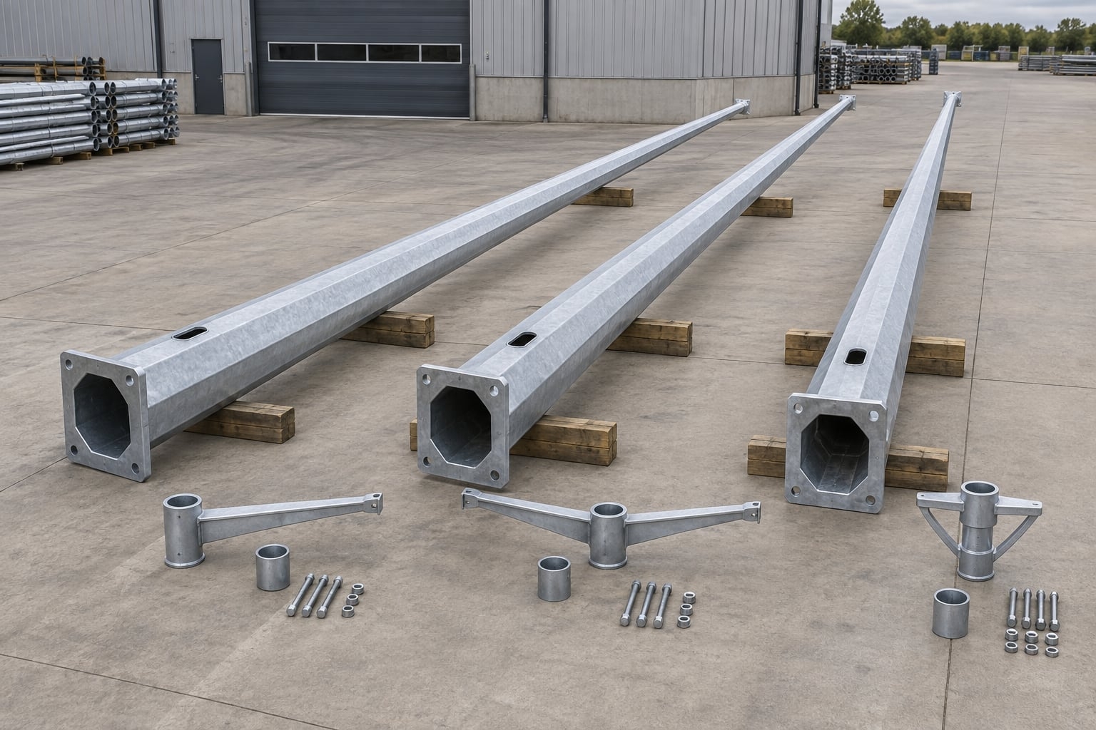
A single arm can project one luminaire toward the carriageway from a verge position. Twin arms can serve a median or two-sided road when supported by the lighting model. A post-top spigot may suit a compact fixture with the correct mounting interface. Straight, curved and upswept arms each change the luminaire coordinate, appearance and exposed area.
State outreach, rise, inclination, tube dimensions, attachment method, mass, projected area and orientation. A longer arm is not only a styling choice; it changes the moment transferred into the pole. When arms are detachable for transport, the approved detail should define engagement, fasteners, anti-rotation, cable route and field assembly.
Provide the exact luminaire model, side-entry or post-top method, spigot dimensions, insertion length, fasteners, cable entry, mass, effective projected area and center of gravity. The pole-top and arm interface must match the offered luminaire rather than a generic catalogue assumption. Small dimensional differences can affect clamping, tilt, cable protection and final alignment.
The approved drawing should show the interface, orientation and permissible adjustment. If the luminaire supplier changes a bracket or housing, resubmit the data before production release. Unplanned site drilling, packing or grinding can damage the protective finish and leaves responsibility unclear. A controlled adapter is acceptable only when it is included in the load and interface review.
Structural selection requires the governing design standard, basic wind parameter, terrain or exposure category, topographic condition, height reference and any risk or importance provisions required by the project. It also requires every attachment. Fixture effective projected area, commonly called EPA, should cover the complete orientation and should not be replaced by the front face area from a photograph.
Include arms, luminaires, signs, cameras, control boxes, decorative elements, banners or planned future equipment. Provide mass and center-of-gravity data because gravity and wind effects enter the load path differently. With defined inputs, the supplier can propose a shaft, base and connection schedule; without them, a generic “wind rating” is not a reliable purchasing basis.
Steel grade is one input to the design. Yield properties, available plate, forming behavior, weld procedure, wall thickness, taper, openings and local reinforcement must work together. A higher grade name does not by itself establish adequacy, and one wall thickness should not be copied across different heights or wind conditions without calculation.
The lower and upper dimensions must provide the required structural properties while allowing a buildable base connection, a practical access opening and the declared pole-top interface. Where one shaft uses more than one wall schedule or segment, transitions should be shown clearly. Avoid vague phrases such as “heavy duty” unless the offer also states the actual design basis and proposed geometry.
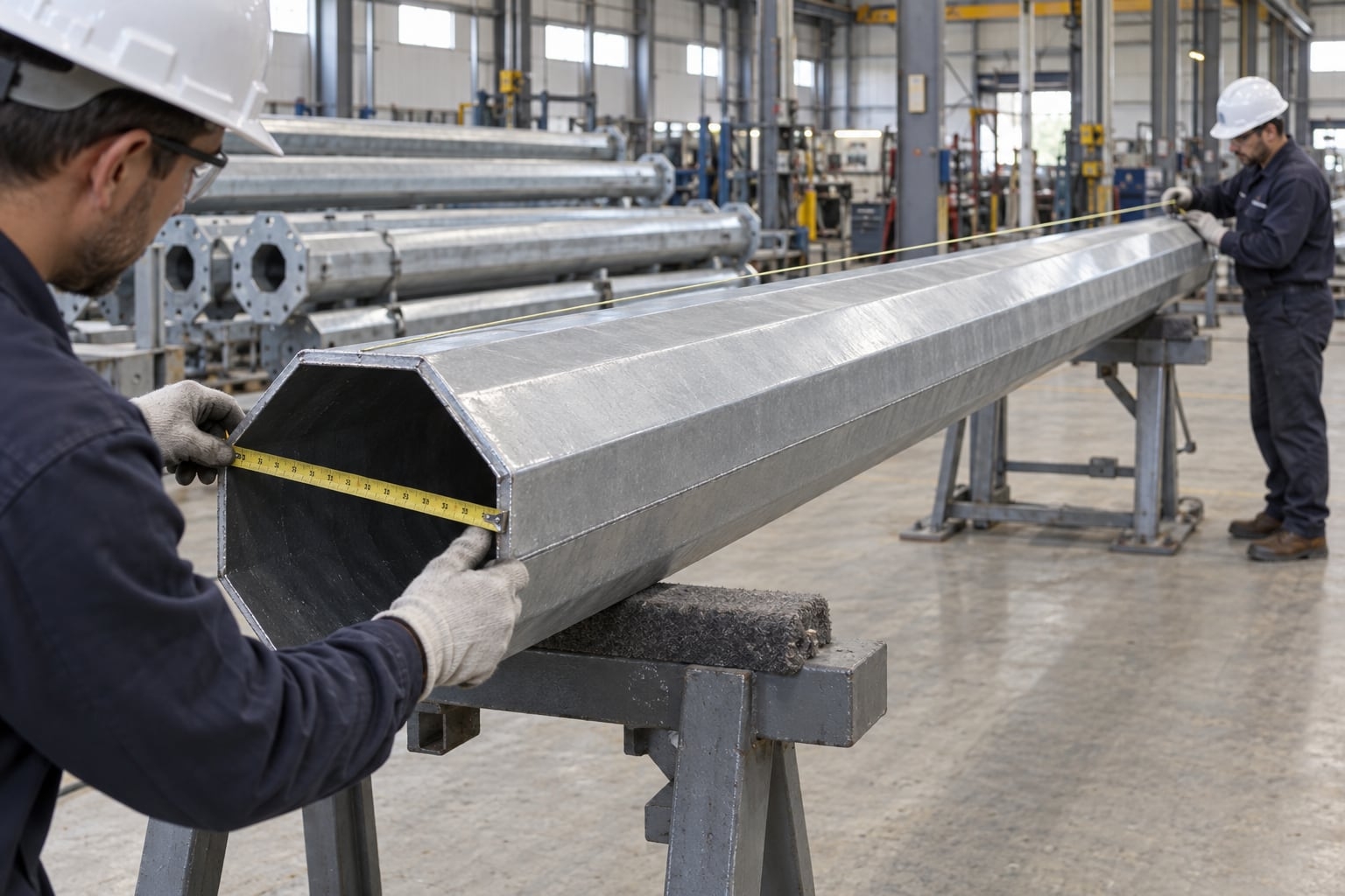
An octagonal cross-section can be measured between opposite flat faces or between opposite corners. Those values are not the same. Drawings and RFQs should identify which convention is used at the base, top and any intermediate checkpoint. Otherwise, two offers may appear to describe different poles when they are using different dimension references.
The dimension convention also affects base covers, clamp brackets, access-door frames and replacement parts. Include a small cross-section symbol or note on the elevation instead of relying on an unlabeled number. During inspection, measure at the defined location and orientation with the shaft supported appropriately.
A tapered blank is formed through controlled bends to create eight faces. Fold positions need to remain straight, and the faces should not twist along the shaft. Forming sequence, tooling, material behavior and dimensional checks influence consistency. The closing edges must align without forcing a corkscrew shape into the body.
Visual inspection from one angle is not enough. Check face width, across-flats dimensions, taper, straightness and corner alignment at agreed locations. A small local change near an opening may be part of an approved reinforcement detail, but unexplained waviness or a rotating facet can affect appearance, door fit and attachment orientation.
The longitudinal seam closes the formed shaft and is part of its structural load path. Joint preparation, fit-up, welding process, qualified procedure, operator qualification and inspection should follow the applicable fabrication requirements. The seam should remain consistently located relative to faces, openings and arm orientation.
Excessive heat can influence straightness, while excessive grinding can reduce local thickness. Cosmetic smoothing is not a substitute for weld quality. Define visual examination and any additional inspection before production. Repairs should use approved methods and remain traceable where the contract requires records.
The arm may connect through a top sleeve, external collar, flange, welded transition or another project-approved arrangement. The detail must carry the declared luminaire and arm loads while maintaining orientation. On an octagonal shaft, a round sleeve or arm tube often needs a deliberate transition rather than being placed against the polygonal shell without support.
Show the mating geometry, engagement, fasteners, welds, cable path, edge treatment and field sequence. Anti-rotation and indexing are especially useful when the arm is installed after delivery. The connection should allow conductors to pass without tight bends, burrs or pinch points and should remain inspectable before final packing.
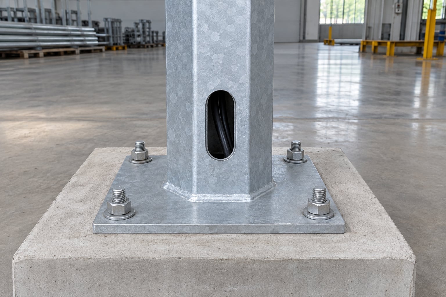
A base-plated octagonal pole transfers force through the shaft-to-plate weld or stiffened connection, base plate, anchors, nuts, washers, bearing or leveling arrangement, grout where specified and the reinforced concrete foundation. These pieces are not independent accessories. The flanged-base light pole guide treats that load path as a procurement interface; changing one dimension can affect the other components and the civil design.
The pole drawing should state plate size and thickness, hole pattern, shaft position, cable opening, weld, any stiffeners and orientation. It should also provide reactions for the responsible foundation designer. Soil, groundwater, frost, drainage, geometry and local code remain project inputs; a standard product photograph cannot establish the foundation.
Issue the approved anchor template and pole-base information before civil construction. Check bolt diameter, circle or rectangular pattern, projection, embedment arrangement, thread protection, conduit position and orientation. A template should hold the anchors during placement without preventing concrete consolidation or creating an unintended obstruction.
Before erection, survey spacing, projection, level and orientation against the released drawing. Do not force a mismatched plate onto the anchors by bending bolts or enlarging holes at site. The street light pole foundation and anchor bolt guide explains the information exchange between pole, structural and civil teams.
A direct-burial pole extends below finished grade and does not use the same lower geometry as a flanged-base pole. Embedment length, below-grade protection, cable entry, drainage, backfill or concrete arrangement and alignment control require project engineering. Adding extra length to a base-plated shaft does not define a proper embedded solution.
Use separate pole marks and drawings for base-plated and embedded units. The direct-burial galvanized street light pole page addresses the anchorless procurement route. Where both options are permitted, compare civil sequence, underground exposure, replacement method, vertical alignment and responsibility for the foundation interface.
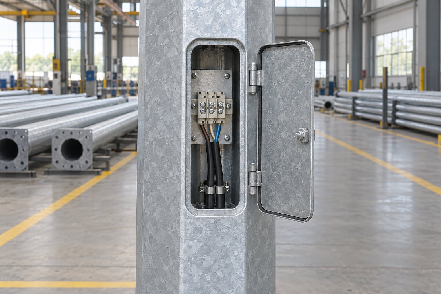
The lower access opening supports cable termination, protective equipment and inspection. Its clear dimensions and elevation should suit the specified electrical components and safe working access. Because the opening removes material from one or more faces, its shape, reinforcement and relationship to the seam and base connection belong in the structural design.
Show door orientation relative to the road, arm and base. The cover should fit the opening, use retained or clearly managed fasteners, and protect the compartment as required by the project. Avoid later site cutting. It can damage galvanizing, create sharp edges and introduce an unreviewed local weakness.
Define how conduits approach the base, pass through the plate or embedded section, reach the access compartment and continue to the arm and luminaire. Cable bends, pulling space, internal welds, sharp edges and sleeve transitions should be checked on the drawing. A hole through the base plate is only one part of the route.
Provide earthing or bonding provisions according to the project electrical design and governing rules. If terminal blocks, fuses, isolators, drivers or control modules are housed in the pole, state their dimensions, mounting method and supply responsibility. After paving or landscaping, the door must remain reachable and removable.
Hot-dip galvanizing of hollow shafts and arms requires vent and drain paths suitable for safe processing and coating coverage. Closed pockets, sealed overlaps and poorly positioned stiffeners can trap liquids or air. Fabrication drawings should show the intended openings before components reach the galvanizing stage.
Drainage provisions also need to remain compatible with field orientation and corrosion strategy. Openings should not be blocked by base covers, grout, arm sleeves or packing materials. Their size and position follow the fabrication and galvanizing plan; they should not be guessed or drilled after finishing without engineering review.
The coating requirement should identify the applicable project standard, preparation, inspection method, sampling, permitted repair procedure and treatment of threads or mating regions. Complete principal welding and approved openings before galvanizing. This reduces damage to the finished protection and helps coating reach the intended surfaces.
Zinc appearance can vary with steel chemistry, geometry and cooling. Evaluate finish against the governing acceptance criteria and functional interfaces rather than judging only color in a photograph. Runs, sharp projections or build-up that prevent door, sleeve or nut fit require controlled attention even when the broader surface remains protected.
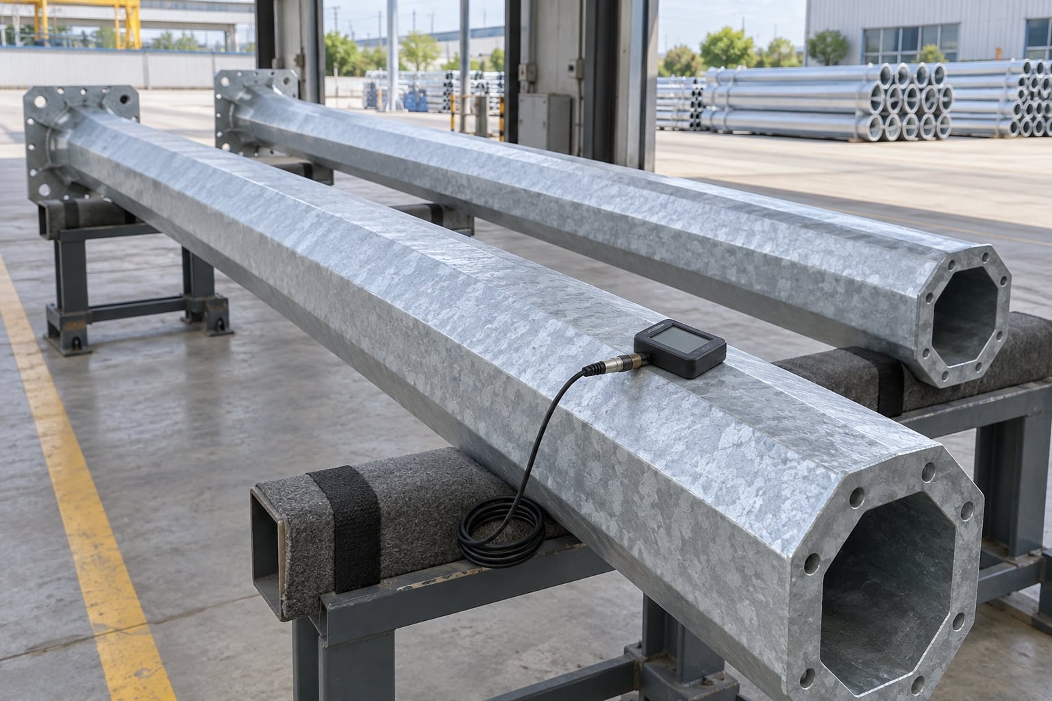
A practical inspection plan can include visual condition, coating measurements at defined locations, vent and drain points, repairs, threaded parts, access covers, sleeves and base interfaces. Calibrated equipment and traceable pole marks make the records useful. A few isolated readings without a sampling plan do not describe an entire shipment.
Recheck critical fits after galvanizing because coating build-up can influence doors, spigots and slip joints. Confirm that fasteners can be installed without removing protection from unintended areas. Where the contract requires dimensional or coating reports, agree the format before manufacture so records can travel with the correct pole batch.
Some projects require a specific color, reduced metallic brightness or an exposure-led duplex system. Powder or liquid coating over galvanizing needs defined surface preparation, product compatibility, application, curing, thickness, masking and repair. A simple instruction to paint galvanized steel does not provide enough information for comparable bids.
State the color reference, gloss or texture, visible acceptance criteria and sample process. Protect threads, earthing contacts, slip-fit regions, identification and drain points as required. Trial-fit or dimensionally check mating components so additional coating thickness does not prevent assembly.
Long octagonal poles may be divided for container loading, inland transport or erection planning. A segmented arrangement introduces a structural and installation interface. Slip-joint profiles must be compatible, and the required engagement, match marks, orientation, field force and inspection should be defined.
A flange joint has its own plate, bolt and fit requirements. Neither joint type should be created only to meet a shipping length after the shaft has been designed as one piece. Coordinate the section break early and include it in calculations, drawings, trial fit, coating protection and site method statements.
A useful general arrangement identifies height reference, shaft length, cross-section, taper, top and base dimensions, wall schedule, arm geometry, luminaire interface, access opening, base plate, anchor pattern, cable route, finish and mark number. Detail sheets then clarify welds, reinforcements, spigots, door assemblies and segment joints.
The project team should review these items together. Architectural approval without checking the luminaire, anchor or civil information can still release an unusable pole. The street light pole shop drawing checklist provides a structured review sequence for consultants, contractors and procurement teams.
Inspection points should follow project risk and specification. Typical checks can cover material traceability, blank dimensions, formed cross-section, taper, straightness, length, seam, opening, base, arm interface, galvanizing, accessories, marking and packing. Define acceptance criteria and record format before manufacture.
Support long shafts properly during checks. Poor stands can create misleading deflection or surface damage. Use the pole mark to link measurements, drawings and packing. Where trial assembly is required, confirm orientation and fit without damaging the final coating.
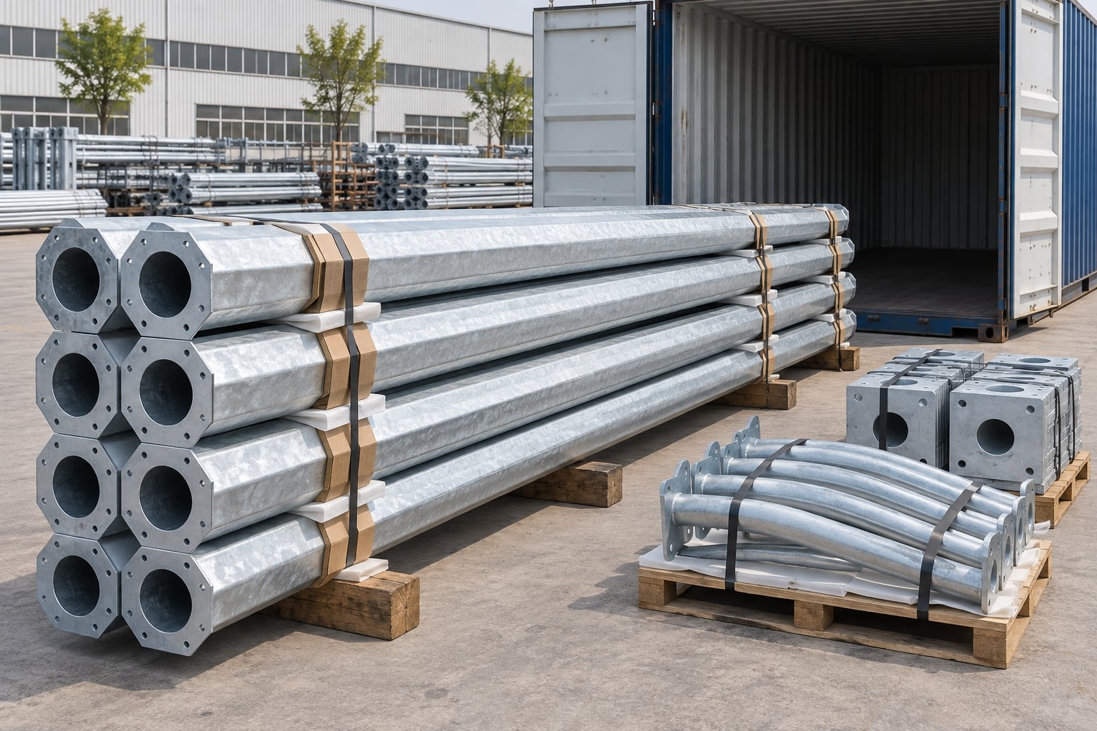
Long galvanized shafts need supports, separators, edge protection and restraint that prevent rubbing, point loading and movement. Arms, base covers and small hardware should be bundled separately, identified by pole mark and protected from loss. Packing must suit the container, handling equipment, inland route and unloading plan.
At site, store poles on level supports away from standing water, corrosive contamination and uncontrolled traffic. Keep identification visible. Do not stack on luminaires, arms, doors or cable openings. A receiving inspection should document quantity, marks, visible damage and missing parts before installation begins.
Erection begins with document control and a task-specific lifting plan. Confirm pole mark, foundation readiness, anchor condition, lifting points, equipment capacity, exclusion zone, weather limit and installation sequence. Use manufacturer information and applicable site rules; do not infer lifting points from a product image.
After positioning, align and secure the pole using the approved base detail, install the arm and luminaire with the defined interfaces, protect conductors and complete electrical checks. Record plumbness, fastener completion, door security, coating touch-up and as-built mark. Use the approved site method statement to organize the full receiving-to-handover sequence.
Pole location should allow future access to the luminaire and lower compartment without creating avoidable conflict with traffic, pedestrians, landscaping or barriers. Check whether the selected maintenance equipment can reach the fixture and whether the access door remains usable after paving and base-cover installation.
Record replacement interfaces for luminaires, arms, doors and electrical components. A controlled pole mark and approved drawing help future teams identify compatible parts. Maintenance planning also includes periodic visual review of alignment, base condition, attachments, access covers, finish damage and unauthorized additions according to the asset owner's program.
A project schedule should give every configuration a stable mark rather than describing poles only by height. One 10 m pole may carry a single arm beside a service road, another may carry twin arms in a median, and a third may support a different luminaire at an intersection. Their structural inputs, orientation and foundation reactions can differ even when the visible shaft length is similar.
Keep the mark consistent across the lighting layout, luminaire schedule, pole drawing, foundation drawing, calculation, inspection record, packing list and site setting-out plan. When a fixture or arm changes, update the affected mark and record the revision. This prevents a late optical decision from silently leaving the old top load in the structural package.
Asset owners often expect future luminaire replacement, yet a new fixture may have a different mass, projected area, center of gravity or spigot. Record the approved interface and loading envelope so later teams know what requires review. A fixture that physically fits the arm is not automatically equivalent from a structural or photometric perspective.
The same caution applies to cameras, signs, seasonal decorations, banners and communications equipment. Additional attachments can increase wind area, create eccentric loads, obstruct the access door or change maintenance access. Provide mounting zones only when they are designed for the intended equipment. Unplanned clamps and drilled holes should trigger an engineering review.
Frequent problems include quoting height without its reference, omitting arm outreach, giving only luminaire wattage, using wind speed without the governing basis, confusing across-flats and across-corners dimensions, and releasing anchor drawings before the pole base is approved. Another error is copying a wall thickness or foundation from a different project because the nominal height looks similar.
Resolve these issues through a marked schedule and a short list of hold points. Require confirmation of loads and interfaces before structural release, base information before concrete work, and approved drawings before production. The process may add a review step early, but it reduces mismatched anchors, unsuitable spigots, site modifications and mixed pole marks later.
A meaningful comparison aligns scope before it compares price. Check whether every offer includes the same pole marks, arm quantities, luminaire adapters, base plates, anchors, doors, terminal provisions, galvanizing, optional color coat, drawings, calculations, inspection records, identification and packing. Differences in exclusions can be more important than differences in one shaft dimension.
Ask suppliers to identify their assumed standard, wind inputs, top loads, material grade, dimension convention and delivery arrangement. Do not reward an unrealistically precise number when the project input is still unknown. A qualified offer should state what is fixed, what remains subject to approval and which information is needed before manufacture.
A useful RFQ states application, quantity by pole mark, height definition, octagonal taper dimensions or design responsibility, arm and luminaire data, complete wind inputs, base type, access and electrical needs, finish, governing standards, documents, inspection, packing and delivery constraints. Attach the lighting layout and interface information where available.
Ask each supplier to list assumptions and exclusions. If information is pending, identify the hold point instead of allowing different silent assumptions. A clear schedule makes technical comparison faster and reduces later drawing revisions. The broader street light pole range can help organize mixed-height or mixed-shape enquiries.
The review starts with the application, pole marks, mounting coordinates, luminaire and arm schedule, wind basis, base concept, finish and delivery route. Jieyao can then identify missing inputs, separate firm requirements from options and prepare a configuration for technical review. Revisions remain connected to the pole mark so drawings, inspection and packing use the same reference.
The aim is a buildable and comparable supply package. Final shaft, plate, anchor and joint details follow the approved project basis, not a generic web-page value. Send the available schedule even if some information is preliminary; clearly identified open items can be resolved before production release.
Keep proposal, approval and production releases traceable to the same pole marks.
| Release stage | Buyer evidence | Open item that holds release |
|---|---|---|
| Technical proposal | Pole type, lighting layout, attachments and wind basis | Unidentified luminaire or wind/exposure assumption |
| Drawing approval | Octagonal dimensions, door/arm, base, anchors and finish | Unmatched civil, fixture or coating interface |
| Production and handover | Released revision, inspections, pole marks and packing list | Unclosed deviation or superseded document in active use |
Its shaft has eight flat faces and eight formed corners, normally with a taper from base to top.
Not automatically. Capacity depends on the complete section, material, wall schedule, openings, connections and loads.
Height is configured to the lighting layout and structural basis. State whether it means shaft, mounting or overall height.
Yes, when the arm geometry, luminaire data, photometric layout and structural design support that arrangement.
Provide model, mounting interface, mass, EPA, center of gravity, insertion length, cable entry and orientation.
A reliable selection also needs the governing standard, exposure, height reference, topography and all attachments.
It can be specified as the primary finish. The applicable standard, inspection and repair requirements should be stated.
Yes. Define the compatible duplex system, color, texture, preparation, masking and acceptance criteria.
They can be engineered separately with defined embedment, protection, cable entry and civil installation details.
Yes, when the slip or flange joint is designed, documented, trial-checked and included in the installation plan.
Approve pole marks, geometry, loads, interfaces, base, access, finish, drawings, inspection and packing requirements.
Send the pole schedule, lighting layout, luminaire and arm data, wind basis, base concept, finish and delivery location.
Send your pole schedule, lighting layout, luminaire data, wind basis and finish requirement. Jieyao will organize the open items and prepare a project-specific configuration for technical review.
Contact Jieyao
Plan a parking lot light pole layout with photometric files, protected pole locations, glare control, structural loads, foundations and maintenance access. Height and spacing are project-specific.
Learn how to choose lighting poles for airports and ports. Understand key selection standards including wind load resistance, corrosion protection, pole height, material choice, and safety requirements for aviation and marine environments.
Compare hot-dip galvanizing, direct-to-steel paint and compatible duplex coatings for street light poles by exposure, detailing, inspection and repair scope.
Compare galvanized steel, aluminum and stainless steel light pole assemblies by structural design, fabrication, corrosion control, finish, handling and inspection evidence. Select materials for the project exposure and approved supply scope.
Compare single arm and double arm street light poles for roads, highways, parking areas, and municipal projects. Learn the differences in lighting coverage, installation cost, application scenarios, and how to choose the right street light pole for long-term project performance.
The best pole for solar street lights depends on wind load, environment, and project scale. Learn when to choose steel, aluminum, or galvanized steel poles for different outdoor lighting applications.
Discover the life expectancy of street light poles based on materials like steel, aluminum, and concrete. Learn how climate, installation quality, and maintenance affect pole lifespan in real outdoor lighting projects.
Learn how to install a solar street light with pole step by step, including foundation construction, pole erection, wiring, and system testing. A practical guide for road lighting, parking lots, and outdoor solar lighting projects.
We primarily use high-strength carbon steel (Q235/Q345/ASTM A36). We also offer premium aluminum alloy and stainless steel poles specifically for coastal regions.
Tapered poles are aesthetic with low wind resistance; cylindrical poles are more cost-effective; polygonal poles (usually 8/12/16 sides) offer the highest structural strength, ideal for high mast lighting.
Our engineers perform mechanical calculations based on your local wind speed data, adjusting wall thickness and base design to ensure the poles can withstand winds up to 160km/h.
It typically ranges from 3mm to 12mm, depending on the pole height, weight of the fixtures, and local wind load requirements.
This is an anti-corrosion process of immersing steel in molten zinc. It provides over 25 years of maintenance-free rust protection in standard outdoor environments.
Yes. We provide complimentary foundation reference drawings, including concrete depth, rebar specs, and bolt positioning data.
We follow AWS welding standards and use Ultrasonic Testing (UT) or Magnetic Particle Testing (MT) to ensure welds are free of pores or cracks.
We hold ISO 9001 (Quality), ISO 14001 (Environmental), and CE certification (EN 40) specifically for the European market.
Yes. We can produce sample poles for craft and color confirmation, though sample shipping costs are typically covered by the client.
Steel poles are lighter, easier to transport and install, have a long lifespan after galvanization, and offer high scrap value, making them more eco-friendly.
Galvanized poles are virtually maintenance-free. We recommend checking anchor bolt tightness and the powder coating surface every 3-5 years.
We provide touch-up paint with each shipment. Simply clean the scratch and apply the paint to restore the appearance.
No. Base plate size and hole spacing are designed based on pole height and stress loads. We provide detailed dimensional drawings for each order.
These are accessories (like anti-climb spikes) installed on the lower section of the pole to prevent unauthorized climbing and enhance security.
Yes. We can flexibly adjust section lengths (e.g., 6m+6m or 5m+7m) based on logistics constraints and on-site installation conditions.
Contact Us
Get a custom lighting solution and quotation for your project. Outdoor lighting manufacturer in Yangzhou, ChinaAbout Jieyao LightingYangzhou Jieyao Lighting Equipment Co., Ltd. is an outdoor lighting manufacturer focused on solar street light systems and high mas... Do you have any questions or requests?
Email: jay@jieyaolighting.com

Click to Chat.
Im online now.