Direct Burial Pole Overview
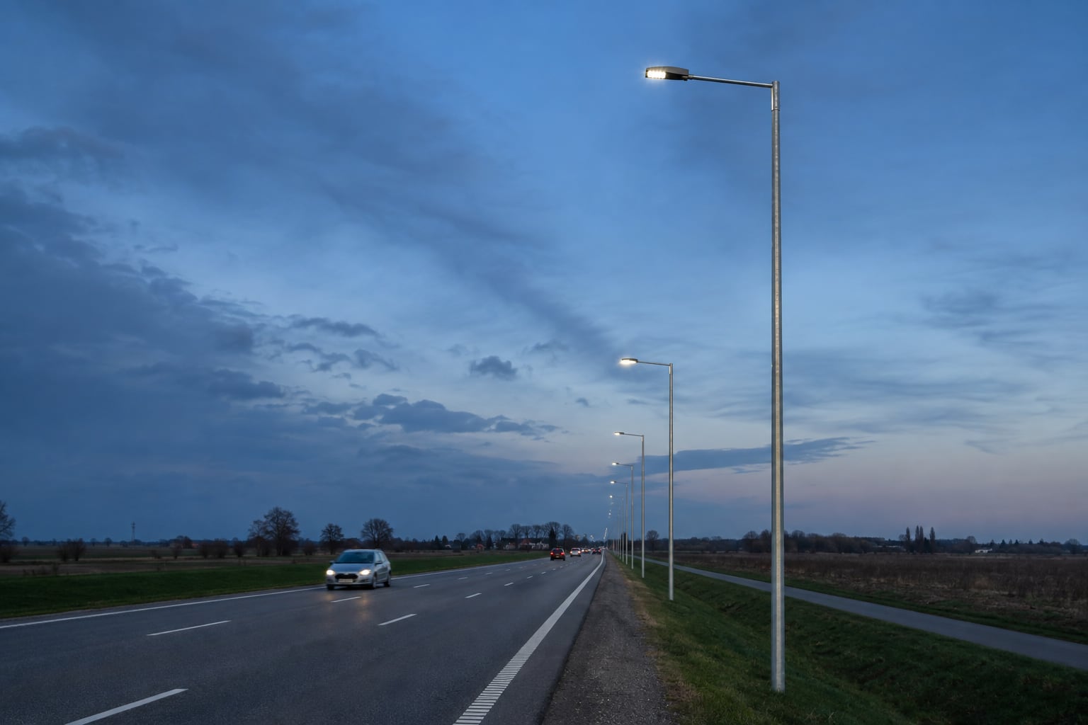
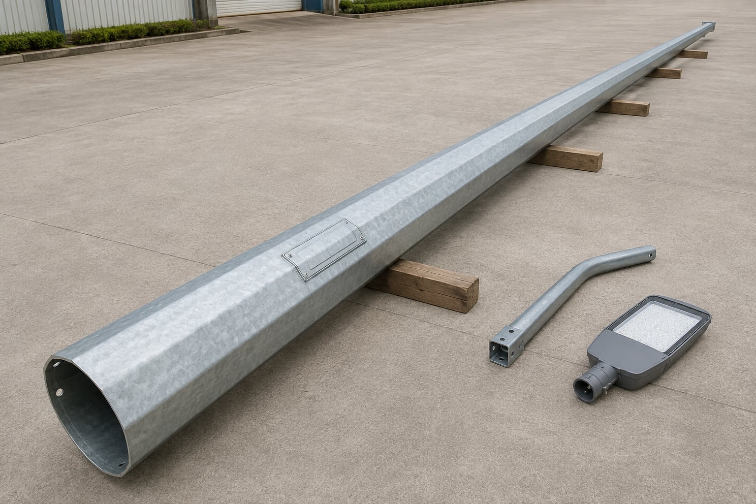
A direct burial street light pole extends below finished ground and develops its support through an engineered embedded section and the surrounding foundation or backfill system. Unlike a flanged pole, it does not use a welded base plate and exposed anchor-bolt connection at ground level. The supplied shaft therefore has a total length greater than its intended above-grade mounting reference.
The absence of a base plate does not remove the need for structural and civil coordination. Embedment depth, lower-shaft geometry, soil or concrete interface, drainage, cable entry and corrosion protection all affect performance. Jieyao configures the pole around the governing standard, full luminaire and arm loads, site wind basis, geotechnical information and agreed installation method. Final dimensions are recorded on an approved drawing.
Procurement should keep three lengths separate: the above-grade shaft reference, any arm rise to the luminaire and the embedded portion. These dimensions influence photometrics, steel quantity, freight and civil work in different ways. A useful schedule also identifies pole station, arm direction and soil-line datum so mixed items can be marked and installed correctly. The direct burial street light pole is then purchased as a defined structural component rather than as an unspecified longer version of a flanged pole.
Where Direct Embedment May Be Considered
Rural and regional roads
Open roadside projects may use an embedded pole where excavation access, soil conditions and authority practice support the foundation concept.
Utility corridors
Direct-buried lighting can coordinate with linear utility work when cable routes, clearances and replacement access are resolved early.
Industrial access roads
Factory and logistics routes may value an anchorless ground interface, subject to vehicle protection, drainage and maintenance planning.
Parking circulation roads
Embedded poles can serve large sites where the civil contractor can control excavation, placement and compacted backfill consistently.
Temporary-to-permanent works
Some programs consider direct embedment for phased infrastructure, but removal, reuse and disturbed-soil conditions still need review.
Authority-specific networks
Utilities or road agencies may have established embedment, access and inspection practices that can be incorporated into the project design.
Project-Configurable Specification
| Item | Configurable scope | Decision basis |
|---|
| Above-grade height | Project-defined shaft or luminaire mounting reference | Road layout and photometric design |
| Total pole length | Above-grade length plus engineered buried section | Support model, soil and installation concept |
| Shaft form | Tapered polygonal, round tapered or specified profile | Structural calculation, tooling and appearance |
| Steel | Q235B, Q355 or approved specified equivalent | Demand, forming, welding and project material rules |
| Top arrangement | Single arm, double arm, tenon or custom adaptor | Fixture interface, photometrics, wind and clearance |
| Buried section | Project-specific geometry and local reinforcement if required | Reactions, support assumptions and corrosion detail |
| Cable entry | Protected opening at an approved below-grade elevation | Conduit route, bending radius and installation sequence |
| Surface protection | Hot-dip galvanizing plus optional compatible barrier treatment | Soil, moisture, salts, abrasion and maintenance |
| Submittals | Drawings and material/inspection records as agreed | Tender, authority and quality-plan requirements |
| Packing | Supported bundles with protected ends and openings | Pole length, finish, quantity and transport route |
Available scope is shown for procurement planning. It is not a universal fixed pole schedule or installation detail.
Direct Burial vs Flanged Base
A flanged pole transfers load through a base plate, anchors and a concrete support. It can be detached by removing the nuts and may simplify replacement where the foundation remains suitable. A direct embedded light pole eliminates that exposed connection but requires excavation or another planned method for removal. Its below-grade shaft becomes part of the structural and corrosion-control system.
Neither solution is automatically better. The comparison should cover governing authority practice, soil, utilities, groundwater, frost, erection equipment, replacement strategy, traffic control, corrosion exposure and civil quantities. A flanged base may suit constrained foundations or bridge work, while direct embedment may suit accessible ground installations with controlled backfill. The foundation and anchor-bolt guide explains the alternative flanged interface.
Commercial comparisons should include the complete installation system. Removing anchors from the pole supply does not remove excavation, support material, temporary bracing, survey or quality-control costs. Conversely, a flanged system includes a cage, template and base hardware that an embedded pole does not use. The lowest pole-only price can therefore point to a more expensive site solution if civil scope and replacement planning are ignored.
Define Above-Grade and Total Length
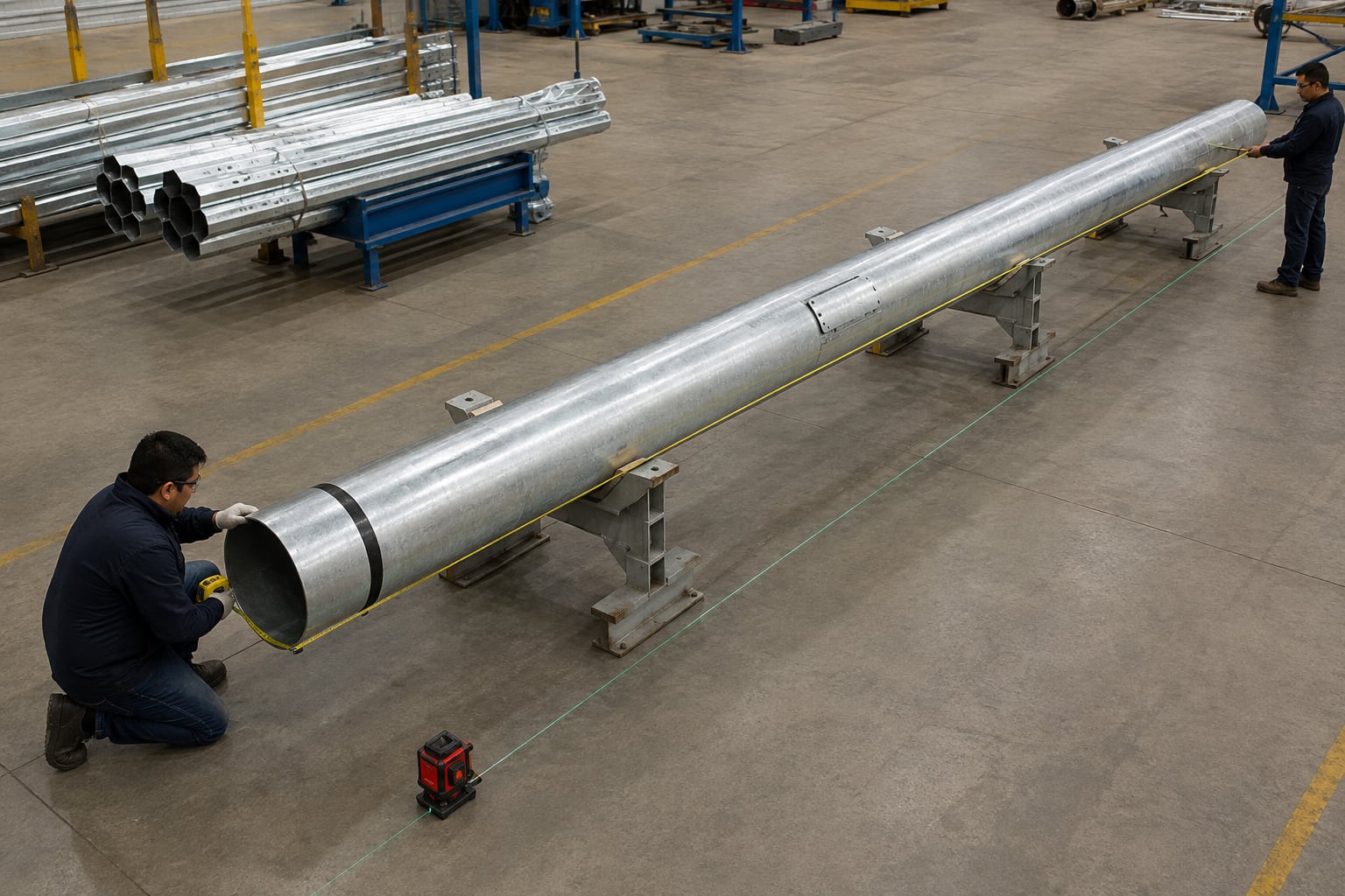
An inquiry should state whether the requested height means shaft length above finished ground, luminaire mounting height or overall height including arm rise. The buried length is added separately to create the manufacturing length. A "10m pole," for example, must not be interpreted automatically as a 10m total shaft if the design expects 10m above ground.
The drawing should identify finished ground, soil-line protection zone, cable-entry elevation, access-door elevation, arm connection and luminaire reference. These dimensions allow the fabricator, civil contractor and lighting designer to use the same datum. Future pavement or landscape level changes should also be considered because they can move the exposure zone relative to the pole.
Structural and Geotechnical Inputs
The pole design requires the governing structural standard, wind-speed definition, terrain or exposure category, topography, above-grade height, shaft form, luminaire weight and effective projected area, arm reach, accessories and service openings. The support design additionally needs soil strength and stiffness information, groundwater, frost, slope, drainage, fill history and the intended backfill or concrete concept.
These data sets interact. A larger luminaire or longer arm increases reactions; weak or disturbed ground can change the required embedded system; high groundwater can influence construction and corrosion details. Assumptions may be stated for preliminary quotation, but production and installation should follow an approved project basis rather than hidden default values.
Embedment Is Not a Fixed Percentage
Rules of thumb that set burial depth as one fraction of pole length may help early discussion, but they do not establish a final design. Required embedment depends on above-grade actions, shaft geometry, soil resistance, backfill or concrete behavior, ground level, local code and serviceability requirements. Two poles of equal height can need different below-grade systems.
The support model should also define how loads transfer along the buried portion and at its lower end. Excavation diameter, backfill material, compaction, concrete placement and construction tolerance can be as important as nominal depth. Jieyao therefore shows the approved embedded length and lower-shaft detail on the project drawing instead of promising one universal value.
Where an authority provides a standard embedment table, the project team should still verify that the table applies to the proposed shaft, top equipment, wind zone, soil class and construction method. Standard details often contain limits and assumptions that disappear when a single depth is copied into an RFQ. Listing the governing detail and edition makes the quotation auditable and gives the installer a clear reference.
Design boundary: the pole supplier can coordinate shaft geometry and reactions; the responsible local civil engineer should verify the embedded support using actual geotechnical and construction inputs.
Shaft Form and Steel Grade
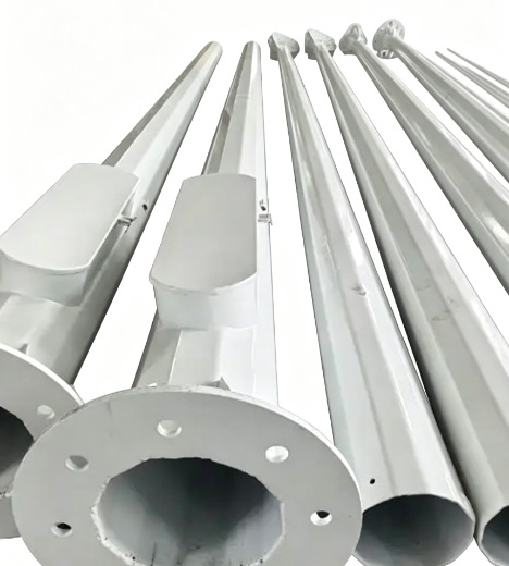
Tapered polygonal and round tapered shafts can both be configured for direct burial. The lower section must remain compatible with the chosen support model, cable opening and protective system. For polygonal poles, dimensions across flats, taper, seam orientation and lower-end geometry are controlled. Round tapered production uses its own forming method and tolerances.
Q235B and Q355 are available subject to project acceptance and sourcing. Higher nominal yield strength does not replace checks for local buckling, service openings, welds, corrosion allowance or serviceability. If EN, ASTM or another material system is required, equivalence should be assessed using properties and fabrication requirements, not matched by grade name alone.
Buried-Section Geometry
The embedded portion is not simply an offcut below the visible pole. Its diameter or across-flat dimension, wall schedule, taper, open or closed lower-end detail, local attachments and transition into the above-grade shaft belong to the approved design. Sharp geometry changes and uncontrolled welded pieces can concentrate stress or complicate coating.
The lower section also needs practical handling and placement. It should pass into the prepared excavation without damaging the protection system, and sufficient clearance must remain for the specified backfill or concrete process. Any anti-rotation or local reinforcement feature should be shown and included in the coating and inspection plan.
End closure is another project decision. An open end may support drainage or processing needs in one design, while a cap or other controlled detail may be required in another. The choice affects galvanizing venting, trapped water, soil entry and installation. It should be resolved before coating; improvised caps or sealed cavities can create manufacturing and field problems.
Cable Entry Below Grade
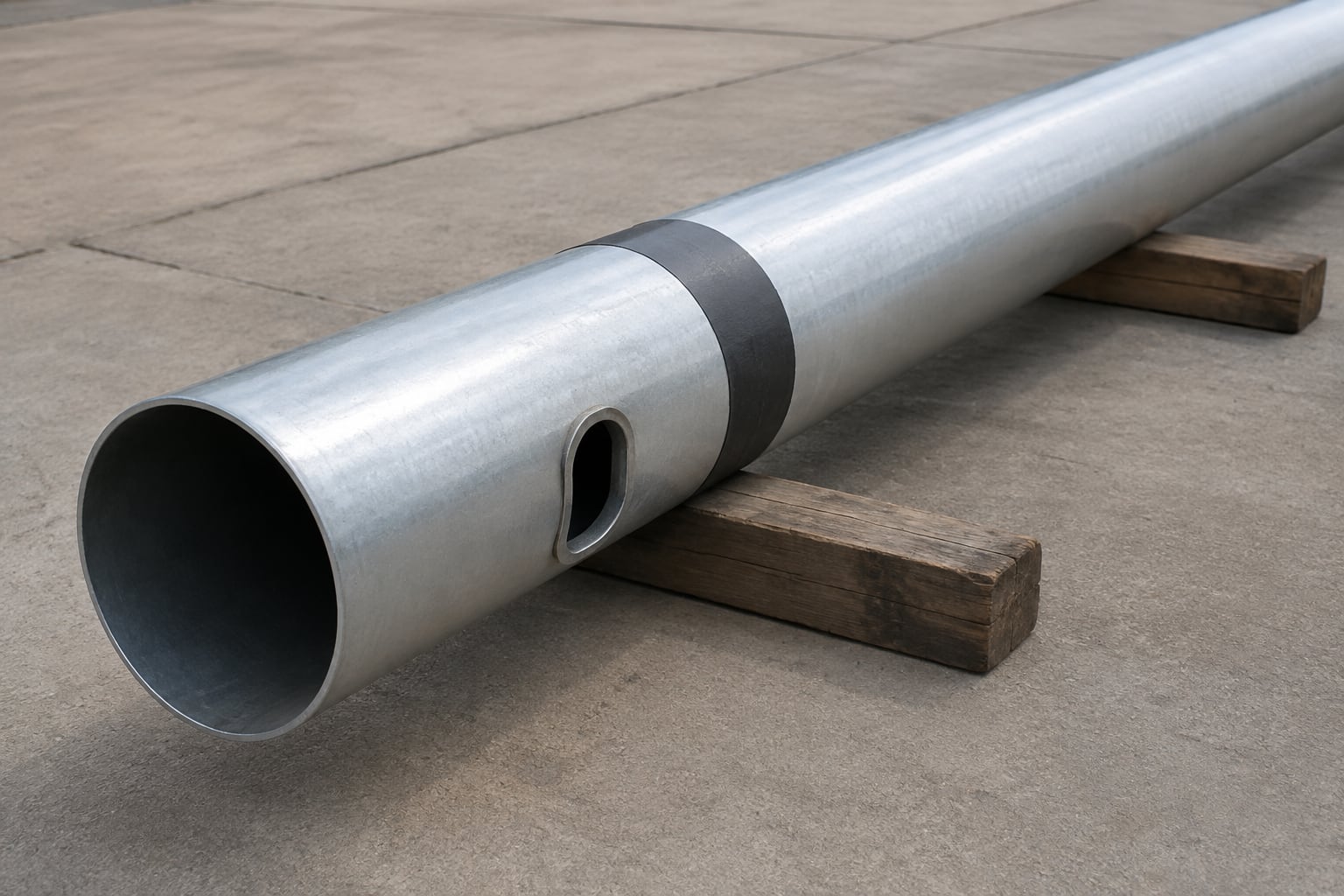
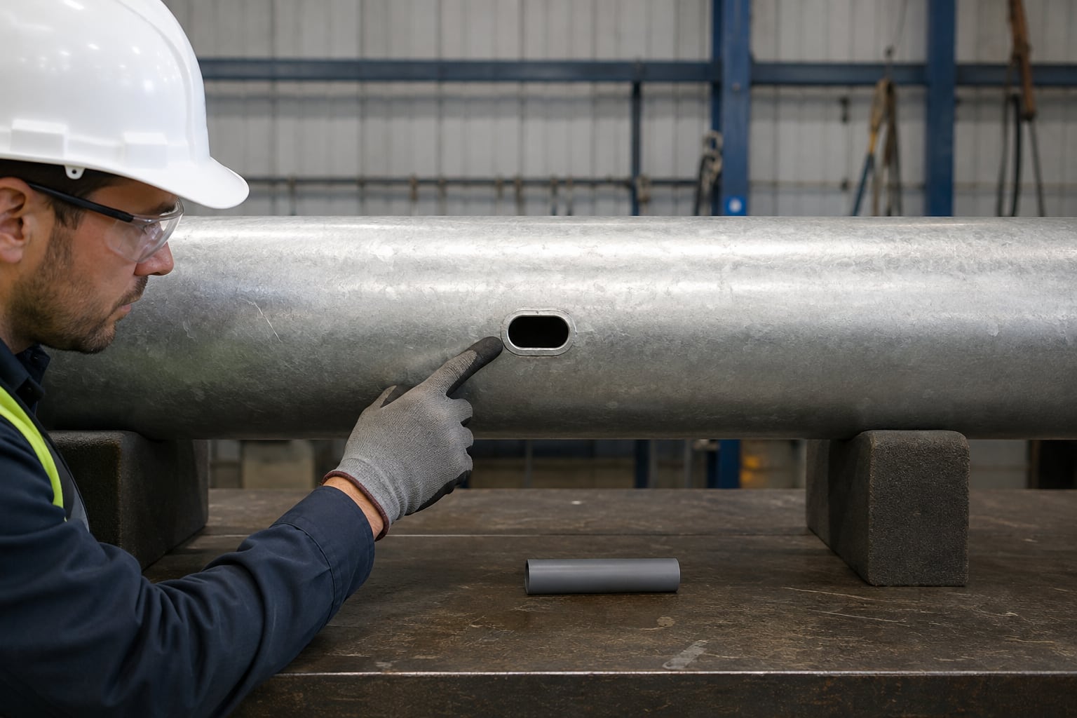
A direct-burial pole commonly receives the supply cable through an opening in the lower shaft. The elevation, size, edge treatment and orientation should align with the civil conduit. Because an opening removes material, its shape and any reinforcement must be considered structurally. A rough field-cut hole can damage galvanizing and create sharp cable edges.
The opening should be low enough for the agreed buried route but high enough to remain practical during installation. Conduit diameter, bend radius and pulling space influence the size and location. Where several circuits or controls are planned, the routing envelope should be provided before the drawing is approved.
Opening orientation should be related to the service door or a survey datum. The civil contractor then knows which side should face the incoming duct before the pole is lowered. Rotating the shaft after it is partly supported can scrape the protection layer or pull a cable. A visible factory mark and matching installation sketch provide a simple control.
Cable Protection and Internal Routing
The conduit and pole opening should form a route that avoids abrasion, crushing and excessive bends. Edges require a suitable smooth detail, and cables may need sleeves or additional protection according to the electrical specification. During lifting, the cable or draw wire must not snag as the pole enters the excavation.
Inside the shaft, separation, support and termination depend on voltage and equipment scope. A cable path through a slip joint, door frame or detachable arm needs specific allowance. The final route should be tested or visually checked before the buried interface becomes inaccessible.
Earthing Provision
The pole can include an internal earthing lug or other agreed bonding point, but the complete earthing system belongs to the project electrical design. Electrode type, conductor size, connection method and testing requirements vary by jurisdiction and network. The below-grade pole surface should not be treated as an automatic substitute for the specified earthing arrangement.
The drawing should show the mechanical provision and cable access without requiring installers to drill the galvanized shaft. Connections should remain accessible through the service door where practical and use materials compatible with the pole environment.
Corrosion Protection at the Soil Line
The transition around finished ground can experience moisture, oxygen, salts, vegetation chemicals, abrasion and changing wet/dry conditions. It deserves explicit detailing rather than assuming the same exposure as the upper shaft. The protection zone may extend above and below the nominal soil line to allow for construction tolerance and future grade changes.
Selection depends on soil chemistry, groundwater, drainage, deicing or coastal salts, landscaping and maintenance. A compatible barrier layer over galvanizing may be specified, with controlled preparation, thickness, cure and repair. No single treatment provides a universal service life in every soil.
Galvanizing and Optional Barrier Systems
Hot-dip galvanizing can protect internal and external steel surfaces when the hollow pole is correctly vented and drained for processing. Coating acceptance should reference the agreed standard and material category. Openings, threads and contact areas may require controlled finishing without removing necessary protection.
Additional below-grade systems may include compatible coatings, wraps or sleeves selected by the project. Their adhesion and continuity depend on surface preparation and handling. A damaged barrier around the most exposed soil line can undermine the intended system, so transport supports, slings and field repair materials should be planned together.
Drainage and Water Retention
Water can enter through condensation, cable routes, an imperfect cap or the surrounding ground. The pole and support detail should avoid creating an unintended reservoir that keeps the lower shaft wet. Any drain path must be compatible with soil, cable protection, pest control and electrical requirements.
Drainage cannot be solved by adding arbitrary holes after production. New openings can weaken the shaft, expose raw steel or let soil enter. The approved design should identify lower-end and opening details, while the civil work manages surface water and grade around the installation.
Soil, Groundwater and Frost
Geotechnical information supports evaluation of lateral resistance, settlement and construction stability. Uncontrolled fill, soft clay, loose sand and rock require different excavation and support approaches. Groundwater can complicate placement, reduce excavation stability and affect corrosion exposure. Conditions may vary along one road near culverts, embankments or utility trenches.
Cold-region projects may need frost-depth and heave considerations. Slopes and drainage ditches change available soil cover and access. If field conditions differ materially from the design report, work should follow the project's review process rather than simply increasing or reducing burial depth on site.
Backfill or Concrete Concept
The surrounding support may use engineered granular backfill, controlled concrete, a combined detail or another authority-approved method. Material, placement lifts, compaction or consolidation, excavation diameter and drainage should be defined by the civil design. The method must be compatible with the pole coating and installation sequence.
Concrete should not be assumed automatically, and loose excavated soil should not be accepted automatically. Each creates a different interface and replacement consequence. If concrete is specified, placement must not displace the pole or trap uncontrolled voids. If compacted material is specified, equipment and lift thickness should achieve the intended uniform support without damaging the shaft.
Field density tests, concrete records or other acceptance checks may be required by the contract. These checks should be planned before installation so access remains available and responsibility is clear. The pole supplier cannot verify an embedded support from a finished-ground photograph alone; hidden-work records connect the installed result to the approved method.
Installation Tolerance and Temporary Support
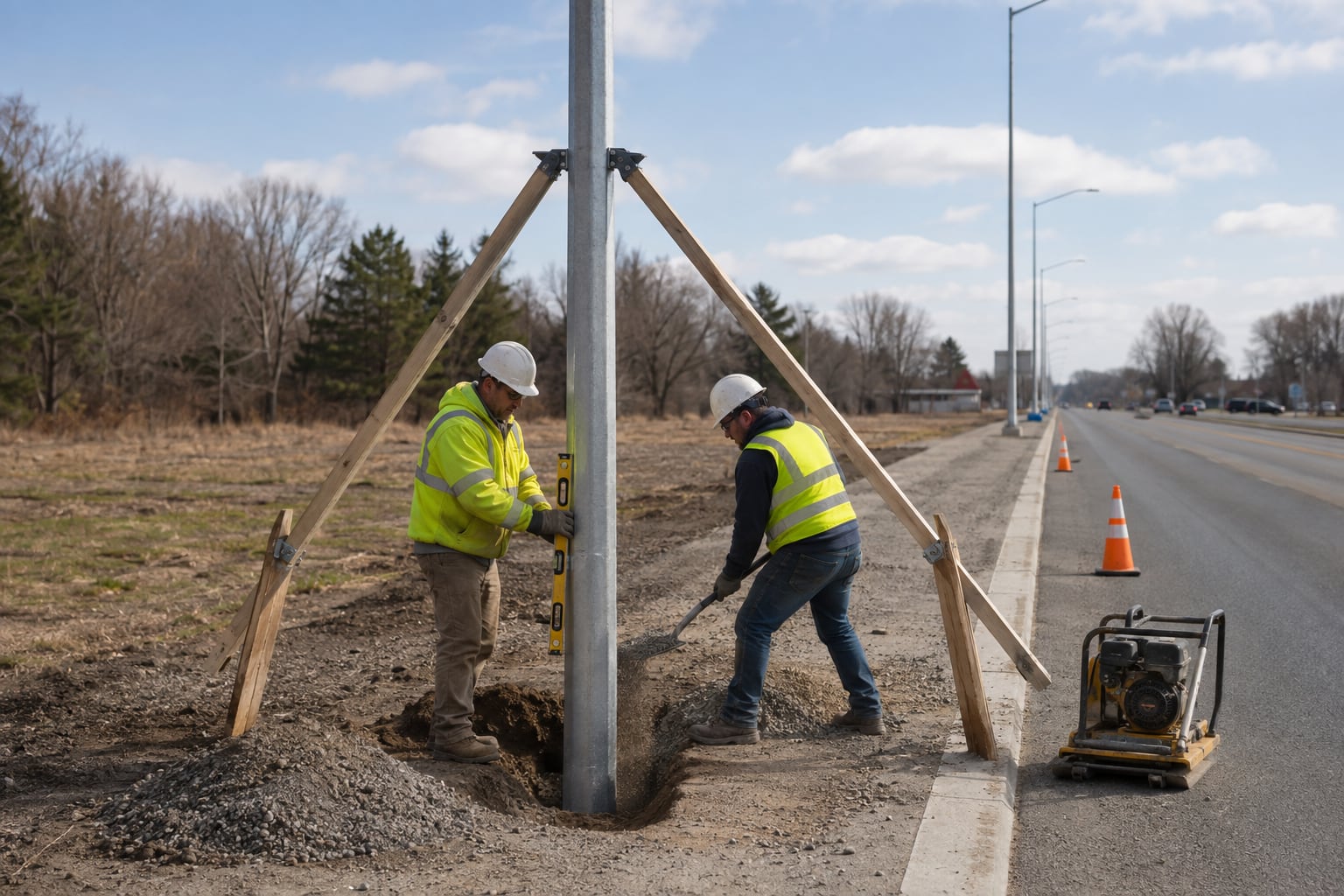
The excavation position, depth and diameter must allow the pole to reach its designed elevation and remain plumb. Temporary braces hold alignment while backfill or concrete develops support. They should connect without crushing the shaft or damaging coating, and their ground anchors must remain stable outside the excavation.
Tolerance affects more than appearance. A tilted pole shifts the luminaire, changes arm orientation and can reduce uniform support. Finished-ground and soil-line protective zones must also line up. Survey references and a defined hold point before temporary supports are removed help control the result.
Arm and Luminaire Interface
Direct burial changes the base, not the need to coordinate the top. Provide luminaire mass, dimensions, effective projected area, center of gravity, mounting opening, insertion depth, tilt and locking method. The arm drawing should define outreach, rise, angle, connection, cable path and orientation.
A single arm may serve a roadside pole; a double arm may serve a median where the embedded system is suitable. Longer, heavier or unequal arms increase bending and torsion. Detachable arms can reduce packing width but require a positively secured, corrosion-protected interface.
Wind Load and Accessory Schedule
A wind-speed number is incomplete without the governing standard, averaging definition, exposure, topography and importance provisions. Open rural roads, coastal routes and raised embankments may be more exposed than sheltered streets. The full fixture and arm arrangement must be included in the design basis.
Cameras, signs, banners, sensors and communication equipment add weight, wind area and eccentricity. Future accessories should not be fitted without review. The inquiry should list the initial equipment schedule and any defined future allowance rather than rely on a generic "heavy-duty" description.
Access Door Position
The service opening should remain above finished ground at an accessible elevation and face a safe maintenance direction. Its frame, reinforcement, corners and cover are structural details. The buried length and changing ground level must not bring the door into the soil or pavement zone.
Internal space can accommodate terminal blocks, protective devices or other agreed components. Equipment dimensions, mounting provisions and cable bend space should be confirmed. A larger opening is not automatically better because it removes more shaft material.
Fabrication and Longitudinal Welding
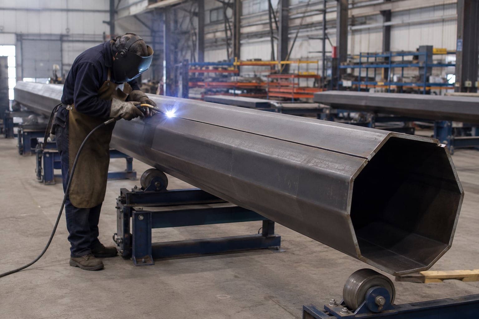
For a formed polygonal shaft, developed plate is pressed and closed by a longitudinal seam. Material identity, plate thickness, forming dimensions, fit-up, welding procedure and inspection follow the project quality plan. The seam should run along the shaft axis; uncontrolled transverse welds or attachments are not substitutes for a designed buried section.
Door and cable openings are cut and reinforced according to the drawing. Straightness, twist and profile dimensions are checked before coating. Weld transitions and local details should remain smooth enough for galvanizing and any additional barrier system.
Coating Preparation and Handling
Galvanized steel should be clean and suitably prepared before an additional organic or wrapped system is applied. The specified process may address surface contaminants, roughness, adhesion, cure and holiday or continuity checks. Compatibility between zinc, primer, coating and repair material matters.
Handling equipment should use protected contact points, particularly around the soil-line band and cable opening. Dragging the lower shaft across concrete or soil can damage the surface before installation. Field touch-up should follow an agreed method rather than a visually similar unqualified paint.
Dimensional Inspection
Inspection can cover total length, above-grade reference, embedded length, top and bottom dimensions, taper, wall schedule, straightness, opening positions, arm interface and protective-zone location. The measurement plan should use the latest approved revision and identify each pole type.
After coating, inspectors can check visible condition, dimensions that affect fit and the agreed coating records. Item marks help match mixed heights and arm orientations. A pole that is only slightly wrong at the buried reference can place its door, arm or luminaire noticeably out of position.
Packing Long Poles
Direct-burial poles may be longer than flanged poles with the same above-grade height. Bundle length, weight, container or trailer limits, route access and unloading equipment should be checked early. Supports must limit point loading and keep straight shafts from rubbing during transport.
Lower ends, cable openings, barrier coatings, doors and top interfaces require protection. Arms and luminaires should be packed separately and identified. Packing lists linked to pole marks reduce the risk of installing the wrong buried length or arm orientation at a foundation location.
Site Excavation and Utilities
The contractor should follow utility-location, permit, traffic-control and excavation-safety procedures. Power, communication, water, drainage and other services may share the roadside corridor. The prepared hole must fit the designed support without damaging a service or forcing the pole away from its photometric position.
Workers should not enter unsupported excavations. Spoil, water control and equipment access depend on soil and depth. If rock, groundwater or unknown utilities are encountered, the project team should review the location or support design rather than alter embedment informally.
Pole Erection and Alignment
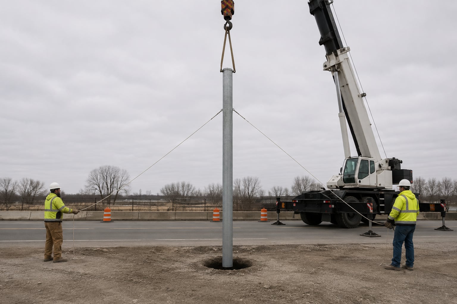
A lift plan should define crane capacity, rigging, tag lines, exclusion zones and the sequence for managing cables. The straight lower end is aligned with the excavation; no worker stands beneath the suspended pole or inside the hole. Coating protection at sling and ground-contact areas should be maintained.
The pole is lowered to the specified elevation and oriented so the door and arm face correctly. Temporary supports hold it plumb while the surrounding material is placed. Installing the arm and luminaire before or after embedment depends on weight, access and the approved erection method.
Wind conditions during lifting need consideration even when the final pole design is adequate. A long bare shaft can rotate or oscillate while suspended, and a preinstalled arm or fixture increases exposed area. The lift supervisor should define weather limits, communication signals and abort conditions. These temporary-stage controls are separate from the completed pole's design wind basis.
Backfill and Placement Quality Control
Granular material is placed and compacted in the specified lifts using equipment that does not strike the shaft. Concrete, when required, is placed and consolidated without moving the pole or leaving major voids. Plumb, orientation and embedded elevation are checked throughout rather than only after support is complete.
Records can include excavation condition, material delivery, lift or concrete information, alignment surveys, protective-system condition and final ground level. Temporary braces remain until the responsible procedure allows removal. Surface grading should direct water away and preserve access to the service door.
Maintenance and Soil-Line Inspection
Inspection frequency depends on environment, authority practice and observed condition. The soil-line zone, coating transitions, drainage, impact damage, shaft plumb, service door, arm, luminaire and nearby ground should be visible where practical. Vegetation, accumulated soil and standing water can conceal deterioration.
Future excavation around the pole must protect the shaft and buried cables. New accessories require structural review. If replacement becomes necessary, the removal plan should address the embedded section, surrounding material, cable isolation and restoration rather than assuming the pole can be unbolted like a flanged base.
Comparing Quotations
Compare above-grade height, total length, buried section, shaft geometry, steel grade, wall schedule, arm, luminaire basis, wind criteria, door, cable entry, galvanizing, soil-line protection, drawings, records and packing. Confirm whether installation or civil support design is included, excluded or based on stated assumptions.
A shorter or lighter pole may simply use a different height reference or embedment assumption. Resolve deviations before purchase. Where a detachable foundation connection is preferred, compare a flanged 10m single-arm pole, 10m double-arm pole or 12m highway pole on the same structural basis.
Ask each supplier to mark exclusions and preliminary assumptions. One offer may include the embedded-length design but exclude site verification; another may quote a shaft from a buyer-provided civil detail. Drawing turnaround, inspection points, coating documentation and packing method also affect delivery risk. A normalized comparison makes these differences visible without forcing every manufacturer into an inappropriate fixed catalogue value.
RFQ Checklist
Application and quantity: road type, pole locations, above-grade reference, quantity, schedule and destination.
Top equipment: arm layout, luminaire mass, dimensions, EPA, mounting interface and all accessories.
Structural criteria: governing standard, wind definition, exposure, topography and required calculations or reactions.
Ground inputs: soil/geotechnical data, groundwater, frost, slope, drainage, utilities and permitted excavation.
Buried interface: support method, embedment design responsibility, cable route, corrosion system and finished ground.
Documents and logistics: drawings, records, inspection points, pole marking, packing, inland route and unloading.
Related Pole Options
The broad street light pole range introduces available shaft and mounting families. Flanged products may be more appropriate where foundations are already cast, pole replacement must be by unbolting, or bridge and retaining structures control the connection. Direct embedment is one project option, not the default for every road.
For salt-exposed roads, the coastal duplex-coated pole covers a separate coating-system procurement intent. The guide to galvanized street light poles explains the general fabrication and zinc-coating basis.
Frequently Asked Questions
What is a direct burial street light pole?
It has an engineered lower shaft embedded below ground instead of a base plate and anchor bolts.
Is total length the mounting height?
No. Total length includes the below-grade section; the height reference must be stated separately.
How deep should the pole be buried?
Depth is project-specific and depends on loads, shaft geometry, soil and the support method.
Must concrete be used?
Not always. The responsible civil design defines concrete, engineered backfill or another approved system.
Is a soil report needed?
Geotechnical information is important for verifying the embedded support and construction method.
Where does the cable enter?
Through a protected lower-shaft opening coordinated with the underground conduit and cable bend.
Is the buried section galvanized?
It can be galvanized internally and externally, with added compatible protection when specified.
Can it be used near the coast?
Possibly, after soil, salt, groundwater, drainage and the corrosion system are reviewed.
Can an embedded pole be replaced?
Yes, but removal requires excavation or another planned method rather than unbolting a flange.
Are single and double arms available?
Yes. Arm arrangement follows the lighting layout and full structural load basis.
Are installation drawings supplied?
The agreed package can show pole references and buried interfaces for civil and installer review.
What is needed for a quotation?
Send height, fixture, arm, wind, soil, support, cable, coating, quantity and destination data.
Request a Direct Burial Pole Proposal
Send the road layout, above-grade height, luminaire and arm schedule, wind criteria, soil or geotechnical information, intended support method, cable route, corrosion environment, quantity and delivery destination. Jieyao will prepare a project-specific pole configuration and interface drawing for review.
Contact Jieyao Lighting