

 English
 Español
 Bahasa Indonesia

- Product details
-
CUSTOM STEEL POLE FABRICATION
Your drawing. A pole assembly built around it.
A road-lighting layout may call for a different arm, a particular base connection or a door positioned around site access. Jieyao quotes steel pole assemblies to your project drawings, with the shaft, attachments and finish defined together.
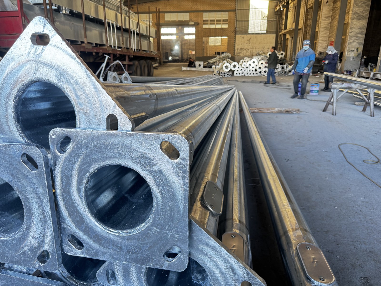
Galvanized pole shafts with flanged bases and service-access covers, prepared for road-lighting assemblies.
What can be made to your drawing?
Shaped for the layout
Specify the shaft profile, overall height, taper and arm arrangement. Round and polygonal sections, single arms and twin-arm layouts can be reviewed against the project brief.
Matched at the interfaces
Set the luminaire connection, base-plate pattern, door position and cable-entry details. These dimensions determine how the pole fits adjoining equipment and civil works.
Finished for the setting
Define galvanizing, an additional colour coating where needed, appearance and packing. Agree the finish and inspection scope with the quotation.
Customise the assembly, from the top connection to the base
Customisation is useful when the mounting position, appearance or site interface differs from a catalogue arrangement. For a new road, the arm can be coordinated with the lighting layout. For a replacement pole, the base and fixture connection may need to match retained equipment. For a campus or commercial development, the shaft proportions, colour and arm form may need to follow an architectural scheme.
Begin with the dimensions that are fixed by the project. The remaining choices can then be reviewed without changing a critical connection elsewhere in the assembly. A pole elevation, an arm detail and a base plan are often more useful than a long list of disconnected dimensions.
Shaft profile and section arrangement
The shaft drawing defines the profile, height reference, taper, upper and lower dimensions, material and wall schedule. Round and polygonal forms create different faces and connection details, while a straight or tapered profile changes the outline along the height. Where a sectional construction is required, show the joint arrangement and assembled height together with the transport limits.
Arm geometry and luminaire connection
Specify arm quantity, outreach, rise and orientation relative to the shaft. The luminaire drawing should identify the mounting diameter, insertion length, fixing arrangement and cable entry. Provide fixture mass and effective projected area—the wind-facing area used for structural assessment—alongside the arm layout. Fixture wattage alone does not describe the load on the pole.
Base plate, access opening and cable route
At the lower end, show plate dimensions, holes, anchor pattern and the position of the access door. A door facing a verge can be easier to reach than one obstructed by a barrier or planting. The opening and internal clearance also need to suit the electrical equipment and cable route. Agree these interfaces before the matching foundation and anchors are released.
Details that deserve a closer look
A drawing-led order is most useful when it resolves the details installers will encounter. The access opening needs room for the specified electrical equipment; the cover must fit the opening; and the base pattern must match the released anchor layout.
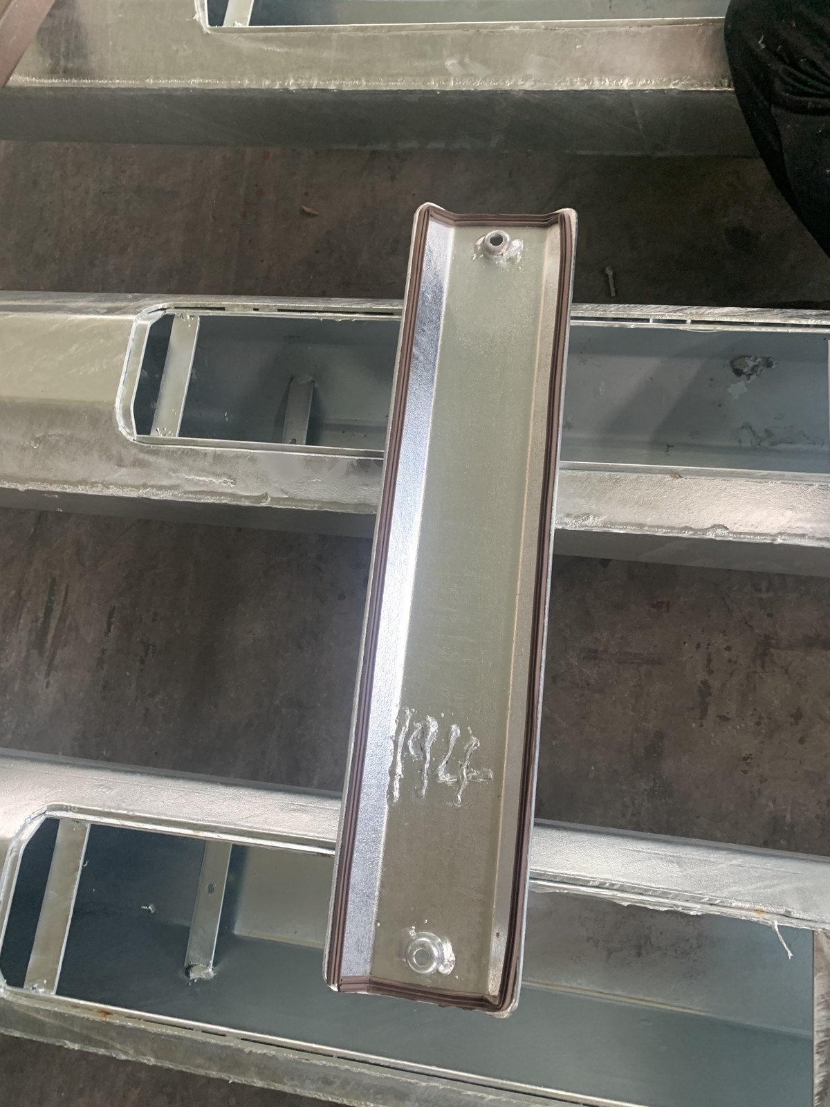
Service access: opening, cover fit and internal clearance form part of the pole drawing.
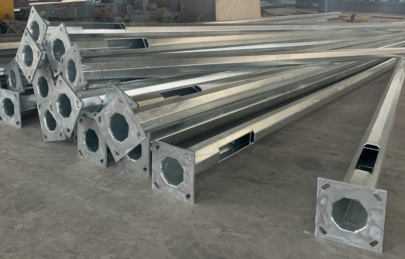
Base connection: shaft profile, plate geometry and bolt pattern are coordinated with the foundation interface.
From an enquiry to a defined supply
01 · Share the brief
Send the latest drawing, quantity, destination and required date. Existing layouts, luminaire drawings and reference photographs help explain the interfaces.
02 · Resolve the details
Review the dimensions, material, loads, attachments, finish and documents included. Record any proposed change against the drawing revision.
03 · Agree the order
The quotation and approved drawings identify the pole components, inspection scope, marking and packing to be supplied.
Material, galvanizing and colour finish
The material grade and thickness belong on the pole drawing and quotation. They are selected with the shaft geometry, openings, attachments and project design basis. A heavier shaft or a familiar grade name, considered on its own, does not establish the capacity of the completed assembly.
Hot-dip galvanizing provides a zinc coating on the fabricated steel. Where a colour finish is required, specify the coating system over the galvanized surface, colour reference, gloss or texture and any masking needed at mating surfaces. The coating specification should also identify the inspection and repair requirements that apply to the order.
For coastal, industrial or persistently wet locations, include the exposure information in the enquiry. Drainage, the base zone, door details, fasteners and finish all affect the corrosion-control approach. Select the system for those conditions rather than using an unqualified service-life figure.
Turn the drawing into an inspectable product
A useful inspection plan focuses on the features that determine fit and assembly. These can include shaft dimensions and straightness, arm position, door fit, base-hole pattern, weld requirements, coating and component identification. The order should state which checks and records are required, including any customer inspection or hold points.
Where parts are supplied separately, specify how they are identified and assembled. Arms, covers, adaptors and anchor templates should relate to the correct pole mark and drawing revision. This makes receiving and installation more manageable when several configurations share one shipment.
Inspection photographs can show workmanship and specific checks. Material records, coating records and other agreed documents should identify the components or batch they cover. Tell us the documentation needed with the enquiry so it can be included in the proposed supply.
Supply scope, packing and delivery planning
State whether the enquiry is for a shaft, a pole-and-arm assembly or a broader component package. Base covers, anchors, templates, internal electrical fittings and luminaires may sit in different supply scopes. Listing them explicitly makes quotations easier to compare and helps the receiving team account for the required parts.
Long shafts and projecting plates require a packing arrangement suited to the selected finish and handling route. Separate loose components should be grouped and identified. Provide destination, unloading restrictions, maximum transport length and any requested shipment split so these constraints can be considered before the construction and packing are fixed.
Lead time and order quantity are quoted against the drawing complexity, finish, inspection requirements and production schedule. Include your required arrival date and identify whether it refers to dispatch, port delivery or receipt at site. An urgent replacement and a phased road project may need different delivery plans.
Have a sketch rather than a full drawing?
Start with what you have. An elevation, the required mounting height, arm layout and photographs can establish the intended arrangement. Include the site location and luminaire model so missing dimensions and design inputs can be identified early.
For a replacement, add measured base and anchor details, door orientation and the existing luminaire interface. Final structural dimensions and foundation requirements follow the project design basis.
Q/321084 JYZM002—2023 company-standard references for relevant constructions. Final dimensions and requirements follow the project design, approved drawing and order.
Reference item Company-standard reference Project confirmation Straight pole section 3–12 m reference range Confirm height and structural design for the project Cantilever pole section 5–12 m reference range Confirm assembly and loading basis Outreach 0.75–3 m reference range Confirm arm geometry and luminaire position Cable inlet 100 × 50 mm reference Check cable route and project interface Base-plate plan 260 × 260 to 1000 × 1000 mm reference range Match anchor layout and foundation drawing Steel material Q235 or equivalent-performance reference; minimum thickness reference 3 mm Confirm material grade and thickness on the order documents Hot-dip galvanized coating 65 μm minimum reference below 5 mm steel thickness; 86 μm minimum reference at 5 mm and above Confirm coating specification and inspection method for the order Access opening examples 260 × 120, 420 × 130, 750 × 250 and 1350 × 350 mm reference options Select only after checking cable, control gear and service access A concise enquiry that gets the review moving
You can send a drawing package or a short pole schedule. Include the project location, quantity for each configuration, height reference, arm arrangement, luminaire information, base interface, finish and required date. Mark any dimension or requirement that is still preliminary.
If the drawing conflicts with the written specification, identify the governing revision or highlight the discrepancy. If you want an alternative arrangement, explain the constraint it should solve—for example, an existing anchor pattern, restricted transport length or a particular luminaire connection. This gives the review a practical starting point.
Choose the right enquiry route
Still choosing the configuration? Browse street light pole options. Already comparing arm layouts? See single and double arm poles.
Let’s review your pole drawing
Send the drawing revision, quantity, site location and finish required. Include the target delivery date and any inspection documents needed.
Request a Drawing-Based Quote -
-