

 English
 Español
 Bahasa Indonesia

- Product details
-
JIEYAO · STEEL CAMERA SUPPORTS
CCTV Camera Poles for Security and Traffic Surveillance
Project-configured steel poles for fixed cameras, PTZ mounting and roadside equipment. Coordinate the shaft, crossarms, cabinet supports and cable access with the equipment you need to install.
Choose the mounting arrangement below, then review the drawing-backed 4 m reference and production information. The pole package includes the agreed steelwork and accessories; cameras, power and networking are listed separately in the quotation.
Send Your Camera and Pole Schedule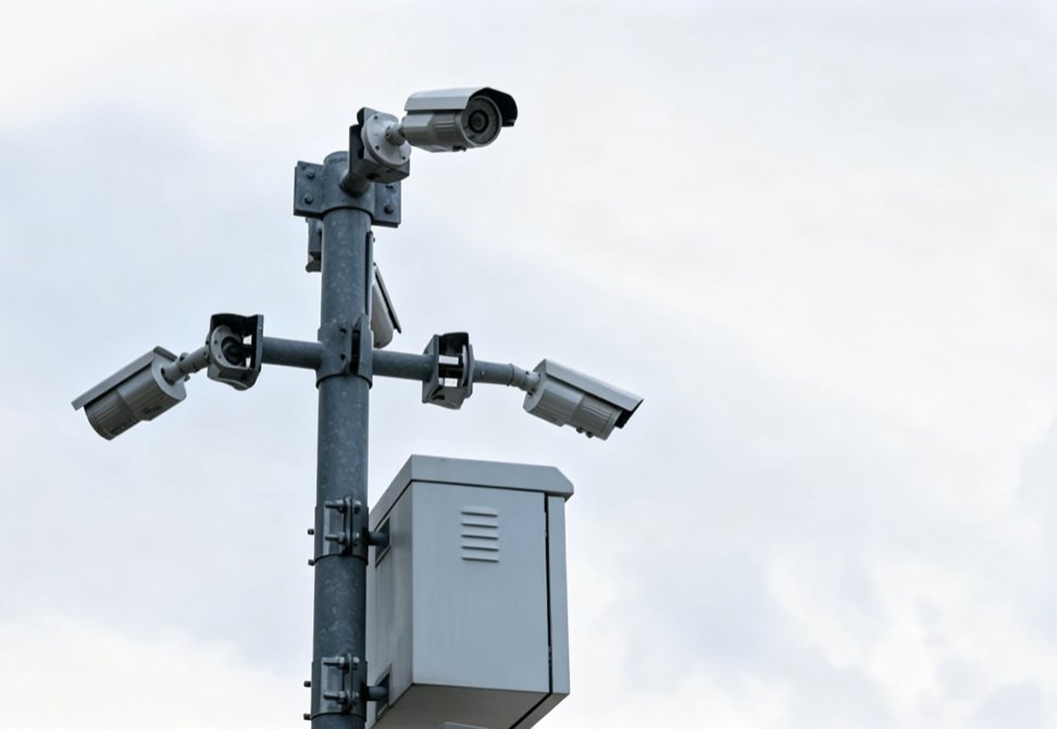
Camera-head and cabinet mounting example.
SupplySteel pole + specified mounting accessoriesConfigurationsFixed camera · PTZ · traffic crossarmDrawing case4 m shaft · 500 mm equipment armFinish referenceGalvanized steel with specified colour finishCamera pole, CCTV pole or security camera pole?
For permanent outdoor video surveillance, these names commonly describe the same steel support family. Select the shaft, arm and connections for the actual equipment rather than choosing a different pole simply because the enquiry uses a different name.
Name used in the enquiry Product scope to identify CCTV pole / CCTV camera pole Support for fixed or moving surveillance cameras, with the required arms and cable access. Camera pole / security camera pole / surveillance camera pole For outdoor security use, the same support family; specify camera position, equipment and service method. CCTV column / camera mast Confirm the physical construction: a fixed shaft, hinged column, lattice tower or telescopic mast are different assemblies. Video surveillance pole / video monitoring pole Describe the monitored area, lens position, adapter and equipment interfaces; video electronics remain a separate scope. Camera pole mount / camera mounting bracket A mounting accessory attached to a pole; identify whether the enquiry needs the bracket, the shaft or both. Looking for a light pole for videos?
For outdoor video monitoring, specify whether you need a dedicated camera pole or a lighting pole carrying both a luminaire and a camera. Show the two mounting positions, electrical routes and maintenance access on one layout. For a combined lighting product, compare our street lighting with CCTV configuration.
A portable filming light stand or photographic extension pole has a different purpose. This page covers permanent outdoor steel supports for surveillance equipment.
PHOTOGRAPHED CONFIGURATIONS
Select the camera mounting arrangement
A security camera pole is selected around the viewing positions and the complete equipment layout. These photographs illustrate different mounting arrangements; they do not mean that every pictured device is included or that the installations share one pole specification.
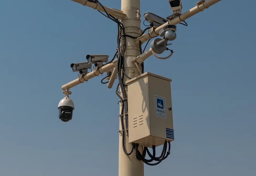
Multi-device and cabinet arrangement.
Multi-device camera pole
Provide separate positions for cameras, illuminators, antennas or a cabinet. Show the mounting level, direction and offset of each item so the head layout can be coordinated with the support.
- Multiple viewing directions.
- Crossarm or side-bracket geometry.
- Cabinet supports and cable connections.
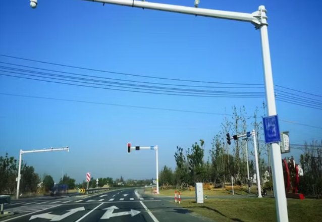
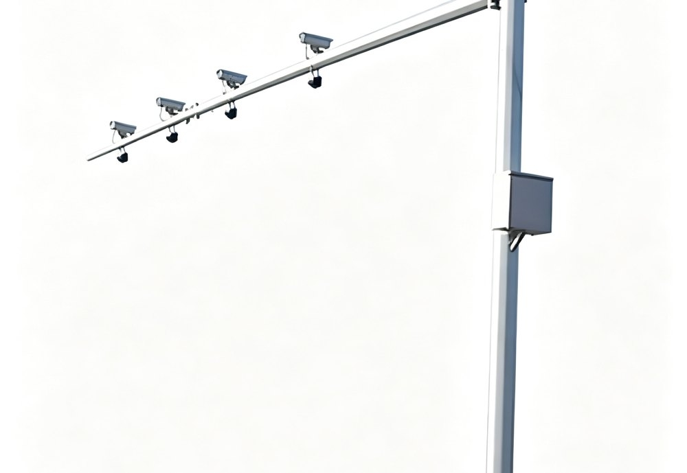
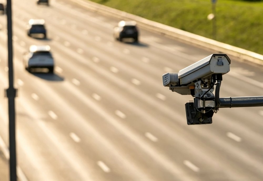
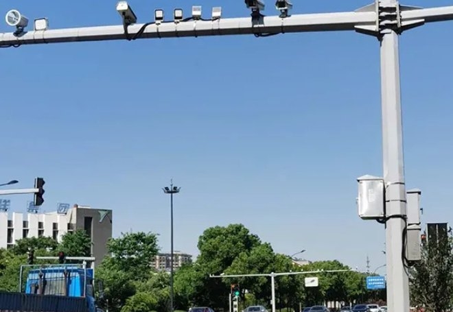
Cantilever camera mounting beside a road.
Traffic camera crossarm
An outreach arm positions equipment away from the shaft or above a monitored lane. Define the camera position from the road layout, then specify the arm, connection and auxiliary device mounts.
- Lane coverage and camera coordinates.
- Arm reach and orientation.
- Equipment weights and projected areas.
PTZ and side-mounted cameras
Preserve the intended view and access to connectors. Identify the bracket pattern and any movement criterion specified by the surveillance designer. Height alone does not establish camera image stability.
- Top, side or short-arm mounting.
- Bracket removal clearance.
- Protected cable entries and service loops.
DRAWING AND SUPPLY DATA
A documented 4 m camera-pole configuration
The Jieyao 4 m surveillance-pole drawing identifies a Q235 steel shaft, a 500 mm equipment arm and provisions for a top solar-panel support with a battery location behind it. The reference supports quotation of a defined steel assembly. Electrical equipment is specified separately.
The associated supply archive also identifies a separate equipment cabinet. Its dimensions belong to that supply example; enclosure protection, electrical contents and environmental ratings are separate specifications.
Use this reference to explain the configuration you need. A different height or equipment layout needs an order drawing with the selected dimensions and mounting interfaces.
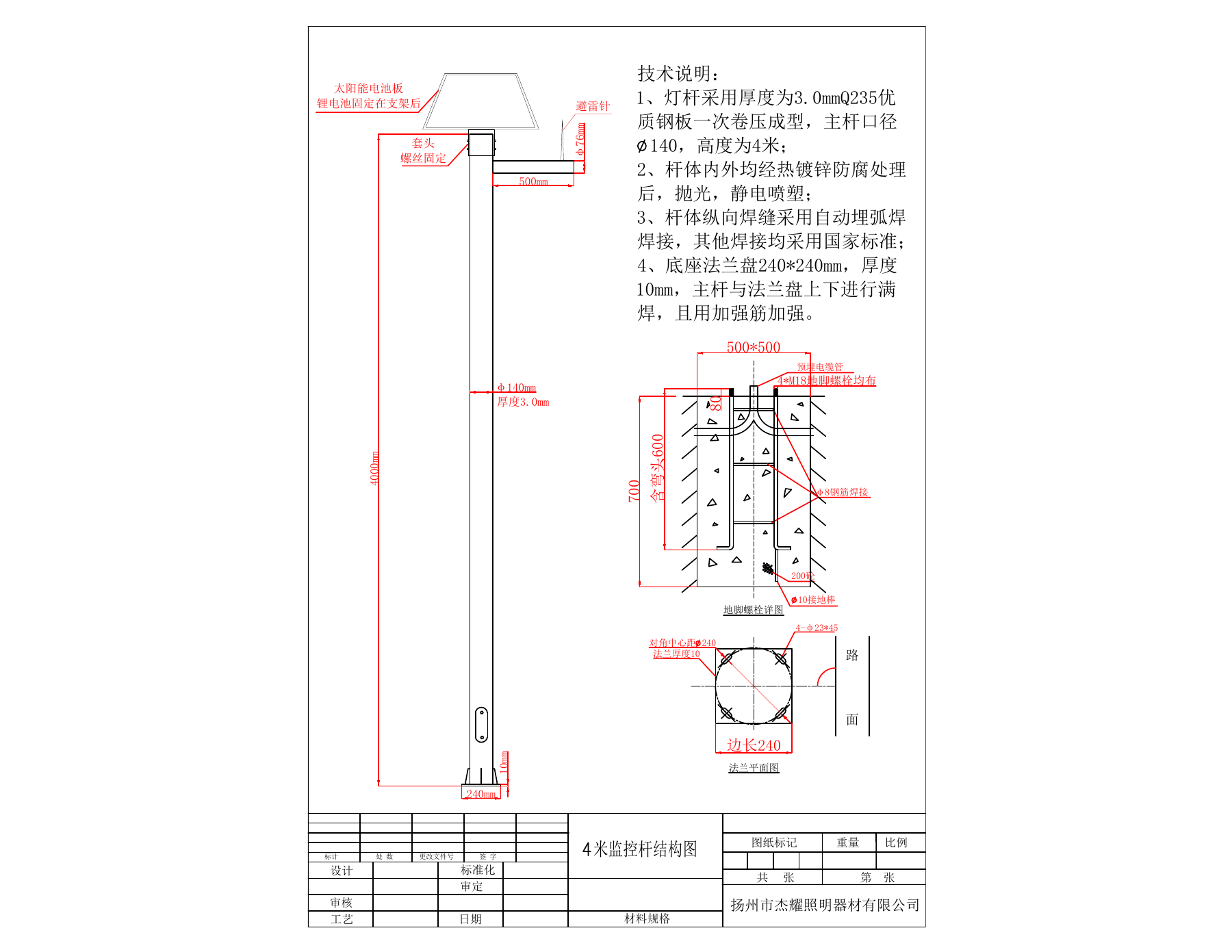
Jieyao 4 m drawing reference. Click to inspect the details.
Item Documented value Ordering detail Main shaft 4,000 mm height; Ø140 mm; 3.0 mm wall From the 4 m drawing, not a complete load rating. Material Q235 steel Match material and thickness records to the selected order. Equipment arm 500 mm outreach; Ø76 mm end detail Confirm the exact bracket and fastening interface. Base plate 240 × 240 × 10 mm The source also contains a diagonal-centre label; release the hole layout on a controlled connection drawing. Fixing slots 4 slots marked 23 × 45 mm Check the hole layout with the selected anchors. Anchor reference 4 × M18; 700 mm overall vertical dimension and a 600 mm bent-length note Use the original detail; it does not establish foundation capacity. Cabinet in the supply archive 500 × 400 × 300 mm Separate cabinet example; no IP rating is established here. Surface-treatment notes Internal/external hot-dip galvanizing, polishing and electrostatic powder coating Specify the current colour, finish criteria and inspection records. PRODUCT CONSTRUCTION
Product details that define the manufactured assembly
Shaft geometry
Select the section profile, height, wall schedule and access opening for the complete camera load. The 4 m drawing provides one round-shaft reference; other configurations require their own dimensions.
Camera brackets and arms
Provide the mounting-hole pattern or adapter drawing for each device. Include direction, reach and bracket position. A camera model name by itself does not define the steel connection.
Cabinet mounting
Define cabinet dimensions, weight, attachment method and door clearance. Coordinate its position with the cable entries and surrounding equipment.
Cable routing and access
Coordinate underground entry, internal routing, outlets, door access and service loops. State cable sizes, bend requirements and any segregation with the system designer.
Base and anchors
Specify the plate and anchors as a matched interface. Identify who designs the foundation and supplies the anchor cage, template, nuts and washers.
Finish and identification
State the protection and appearance requirements. Record pole marks and loose accessories so similar brackets, arms and shaft sections can be matched at site.
Camera stability starts with the equipment layout
Camera movement requirements depend on the surveillance task, lens, viewing distance and processing method. Ask the system designer to state the relevant movement or alignment criterion. Do not replace it with a generic camera-count or wind-speed promise.
Identify every mounted item, including arms, panels, cabinets and future attachments included in the agreed design. Their weights, projected dimensions, offsets and elevations allow the support and foundation to be reviewed on the same basis.
Buyer input Provide with the enquiry Effect on selection Device schedule Exact models, quantities and mounting details Defines brackets and attachment positions. Mechanical data Mass, centre of gravity, projected area and offsets Connects equipment data to structural review. Surveillance task View directions, target areas and specified movement limits Coordinates camera position and support behaviour. Site criteria Wind basis, exposure and supporting-structure information Defines project design inputs. Service method Equipment removal and required lifting or lowering access Resolves maintenance of the selected assembly. PRODUCTION EVIDENCE
Manufacturing and inspection information
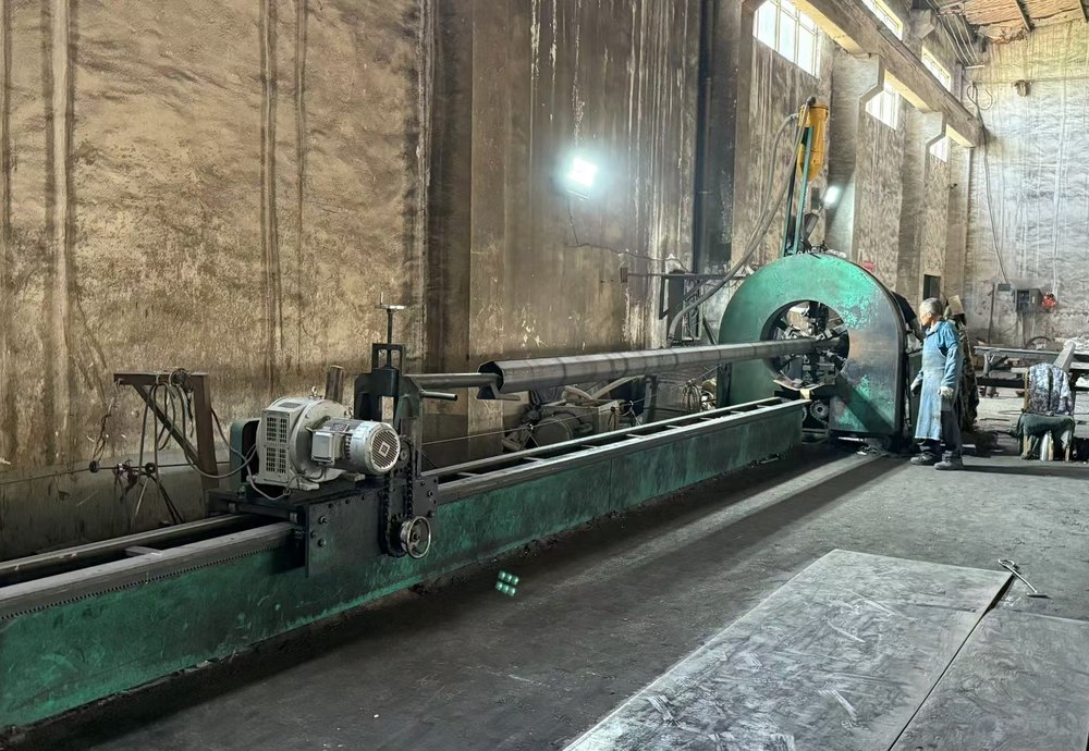
Pole-shaft welding example.
The reference photograph illustrates shaft processing; it is not presented as a verified Jieyao production-site photograph. Jieyao enterprise standard Q/321084 JYZM001—2023 describes dimensional checks, material verification, visual weld examination, sampled weld examination by the specified methods and coating inspection.
Those documents define a manufacturing and inspection basis. Order-specific records show what was inspected on the supplied assembly. Agree the drawing revision, criteria and document list before production.
Reference Documented criterion Scope Material, clause 4.6 Q235 or similar properties; thickness ≥3 mm The selected grade and wall schedule belong on the drawing. Straightness, clause 4.3.1 Not more than 0.3% of pole length Enterprise reference, not a camera movement guarantee. Zinc coating, clause 4.5.2 At least 65 μm below 5 mm metal thickness; at least 86 μm at 5 mm and above Actual readings belong to the supplied batch. Weld examination, clause 5.2 Visual and sampled ultrasonic or magnetic-particle examination as specified No claim of 100% NDT for every pictured pole. Release, clause 6 Factory quality inspection before release Request the agreed conformity and inspection documents. Surface protection and inspection access
Match the coating system to the exposure and appearance requirement. For a galvanized and coloured pole, state preparation, coating scope and repair criteria. Check base edges, welded brackets, openings and interfaces in the agreed inspection plan.
The photograph illustrates coating measurement. Its individual display does not establish batch acceptance; request the recorded readings, locations and applicable criterion for the supplied steelwork.
Keep cabinet doors and access covers reachable after brackets and cables are fitted. Resolve mating surfaces and electrical bonding provisions with the specified finish.
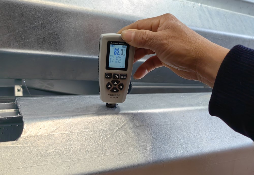
Coating-thickness measurement.
REAL APPLICATION PHOTOGRAPH
Application context: several cameras on one support
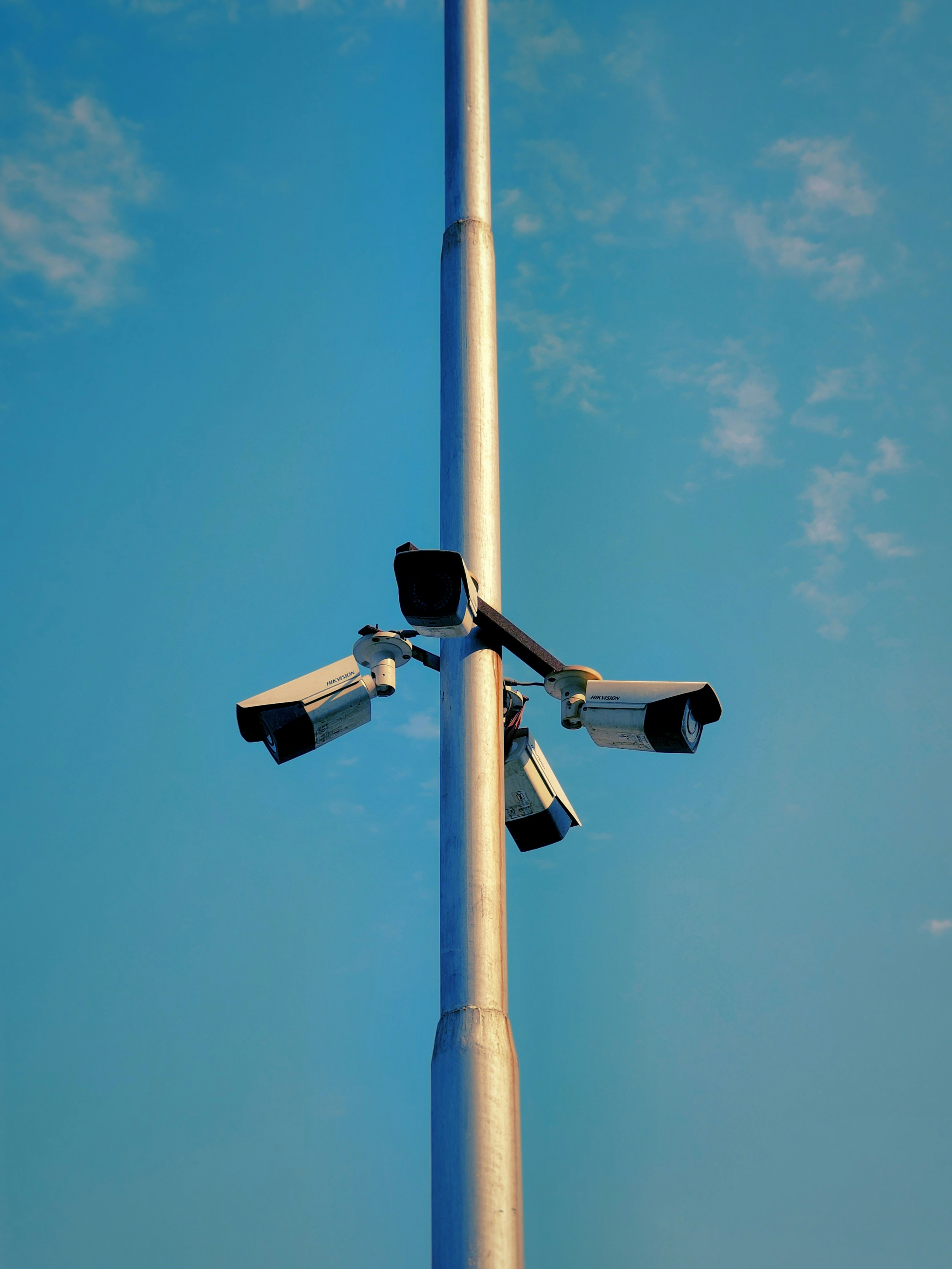
Application photograph: Karan Suthar, Unsplash · Unsplash License.
This urban installation illustrates several camera directions around a shared support. It supports discussion of attachment positions and cable routing; it is an application example, separate from the Jieyao 4 m drawing.
For a road, yard or perimeter project, identify viewing zones before positioning the pole. Check obstructions, traffic clearance, service access and power/network locations. The system designer selects the devices; the pole schedule carries their mechanical data into procurement.
Where a panel support is required, include module outline, elevation and orientation. Panel wattage does not describe wind area or the structural load at the pole.
From pole schedule to delivery
1 · Define scope
List the steelwork, brackets, cabinet supports, anchors and documents. Mark camera, power, cabling and installation responsibilities.
2 · Coordinate drawing
Confirm equipment geometry, camera directions, access opening, cable exits and base orientation against the layout.
3 · Verify materials
Link material requirements and certificates to the shaft, plates and accessories. Resolve substitutions before fabrication.
4 · Inspect interfaces
Check dimensions, arm direction, bracket fit, access and fastening details against the released drawing.
5 · Inspect finish
Use agreed visual and thickness criteria. Associate readings and repairs with the relevant order or batch.
6 · Identify and pack
Mark parts for each pole position, protect the finish and include assembly and inspection information.
Define the quotation package
Send a position layout, device schedule, mounting details, heights, arm reaches, mechanical data, site criteria and finish requirements. Include cabinet dimensions and the civil connection information if those items are selected.
Package Define in the quotation Outside interface Steelwork Shaft, plate, arms, brackets, cover and fittings Devices and final viewing geometry. Cabinet provisions Support clamps/frame; enclosure if included Contents, power supplies, network equipment and heat management. Foundation Plate layout and named anchor components Foundation design, soil information and civil installation. Electrical provisions Agreed entries, earthing provisions and accessories System wiring, power, networking and commissioning. Documents Drawings, inspection records, identification and packing Project reviews, witnessing and authority submissions. For replacement work, send existing base and attachment measurements. Confirm compatibility before ordering; matching heights do not guarantee matching interfaces.
Send Your Camera and Pole ScheduleCCTV camera pole questions
Are CCTV and security camera poles different products?
The names overlap. Select the support by its equipment, geometry and service needs. This page covers steel support and specified accessories; the quotation identifies additional system equipment.
Can the pole carry fixed and PTZ cameras?
It can be proposed when devices, brackets, mechanical data and positions are reviewed together. Photographs do not establish a universal camera count.
Is the 4 m drawing also a 5 m or 6 m specification?
No. Another height needs its own shaft, arm, base and equipment schedule.
Are solar panels, batteries and cameras included?
Only when listed in the quotation. A support bracket or battery location does not establish electrical capacity or autonomy.
Can an existing bracket or foundation be reused?
Provide its dimensions and condition information. The selected connection and supporting structure require a compatibility check.
What proves delivered quality?
Use the released drawing, agreed criteria and order-specific records. Factory photographs and the enterprise standard do not replace inspection of the supplied configuration.
Can a lowering arrangement be added?
A hinge or lowering mechanism is a separate configuration change, requiring a coordinated shaft, restraint, equipment schedule and operating method.
Related pole configurations
Compare custom steel poles for drawing-specific work and folding and tilting poles for a maintenance-lowering arrangement. A lighting product with an integrated camera belongs to the separate smart street light with CCTV scope.
Device schedule and mounting interface
List every camera, illuminator, radar, antenna, sign or cabinet separately. Include device model, quantity, dimensions, mass, projected area, bracket type, orientation, cable connector and service method. Show the mounting-hole pattern and fastener interface on the drawing; avoid relying on a catalogue photograph to establish the dimensions. If the supplier provides only the steel pole, state which devices, brackets, cabling, cabinets and commissioning work are outside that scope.
A shared pole can reduce the number of separate supports, but it concentrates attachments and maintenance tasks at one location. Check whether each device can be accessed without obstructing another view, and identify any cabinet door swing, ladder or lifting access requirement. Define the equipment supply boundary between the camera integrator, pole supplier, electrical contractor and civil contractor.
Change control when cameras or accessories are substituted
Camera and sensor models can change during procurement. Before accepting a substitute, compare its envelope, mass, projected area, mounting orientation, connector and cable requirements with the approved pole drawing and structural schedule. A similar appearance or product family does not prove that the new device uses the same bracket or imposes the same load.
Record the original and proposed device identifiers, the reason for substitution, affected pole points and the reviewing parties. If the change affects arm geometry, bracket holes, wind area, cable routing or access, update the drawing and seek approval from the responsible designer before fabrication or installation.
Handover between the pole supplier and surveillance integrator
Define the physical hand-off point in the purchase documents. The pole supplier may provide the steel support and agreed brackets, while the camera integrator supplies devices, aiming, network settings and system acceptance. If either party provides cabinets, connectors or cables, identify model, quantity, destination and installation responsibility explicitly.
At site, align pole identifiers with camera-point numbers and the device schedule. Record the final orientation and any approved field changes. This keeps structural records connected to the operational system without implying that the pole supplier is responsible for video performance, network availability or security configuration.
Related drawing-configured camera pole
Compare the 5m CCTV pole with panel and equipment-box supports for its distinct shaft, arm and mounting-level arrangement.
PTZ camera mounting configuration
Compare PTZ camera poles with side arms for camera adapters, cable access and a documented eight-metre fixed support. This is a specific mounting arrangement within the camera-pole family.
-
-