

 English
 Español
 Bahasa Indonesia

- Product details
-
JIEYAO · FIXED STEEL CAMERA SUPPORT
PTZ Camera Poles with Side Arms for Outdoor Surveillance
Steel PTZ camera poles provide an elevated mounting position for pan-tilt-zoom surveillance cameras. A side arm places the camera adapter away from the shaft while internal cabling and a base access door support installation and servicing. Select the camera interface, viewing position and equipment arrangement as one assembly.
Specify the camera adapter, equipment position and base connection with the pole. This configuration is a fixed support; the camera, power equipment and any lowering mechanism are separately specified.
Request an 8 m Camera Pole Quotation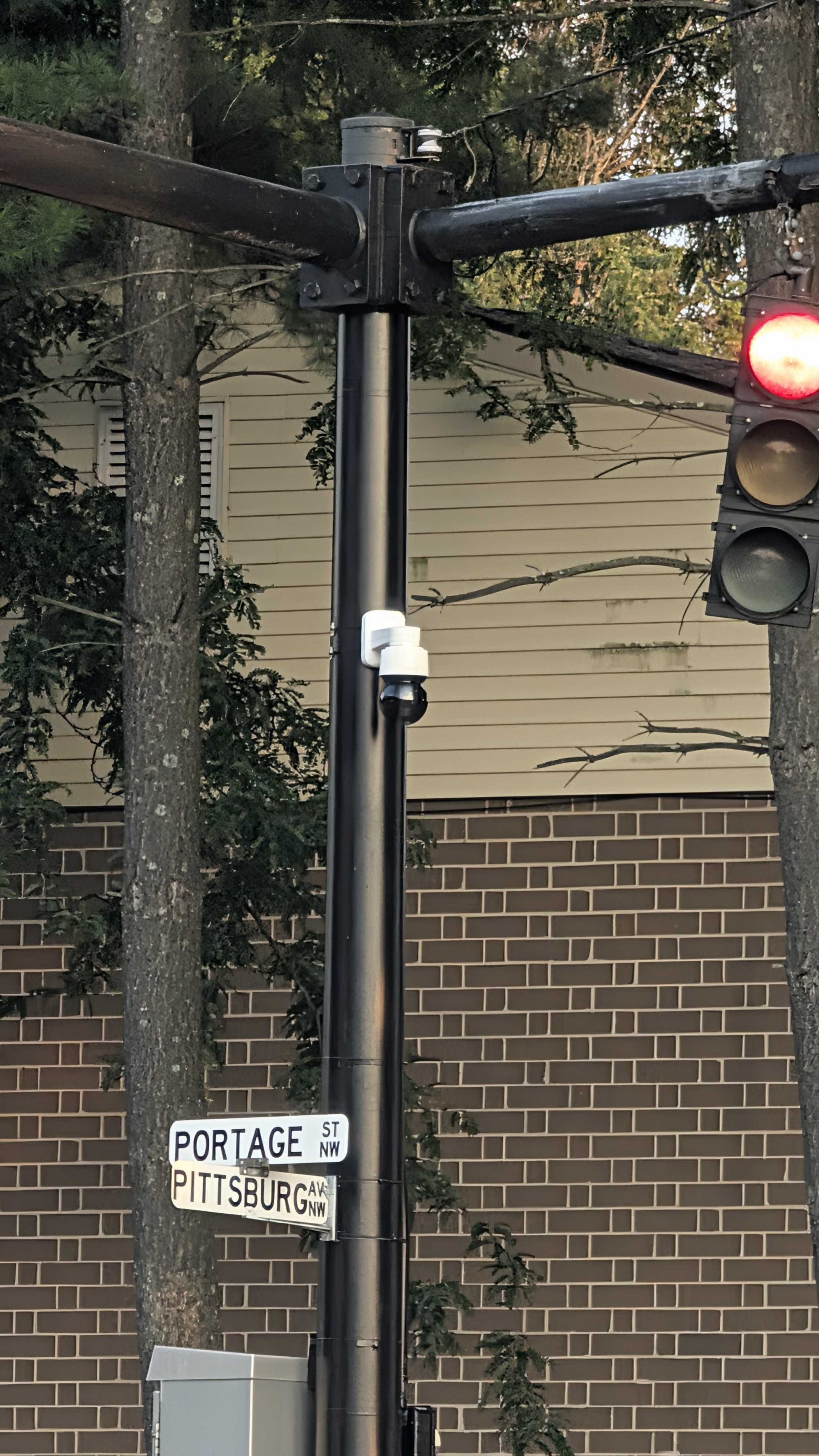
PTZ camera mounting in an outdoor setting. Shakalaka67 / Wikimedia Commons, CC0; application example, not a Jieyao installation.
Documented configuration example: the following dimensions describe the 8 m Jieyao reference, not every PTZ pole.
SHAFT HEIGHT8,000 mmSHAFT SECTION180 mm diameter · 3.5 mm wallMATERIALQ235 in the drawing notesSIDE ARM500 mm reach · 76 mm end detailPTZ mounting: define the adapter before the pole is fabricated
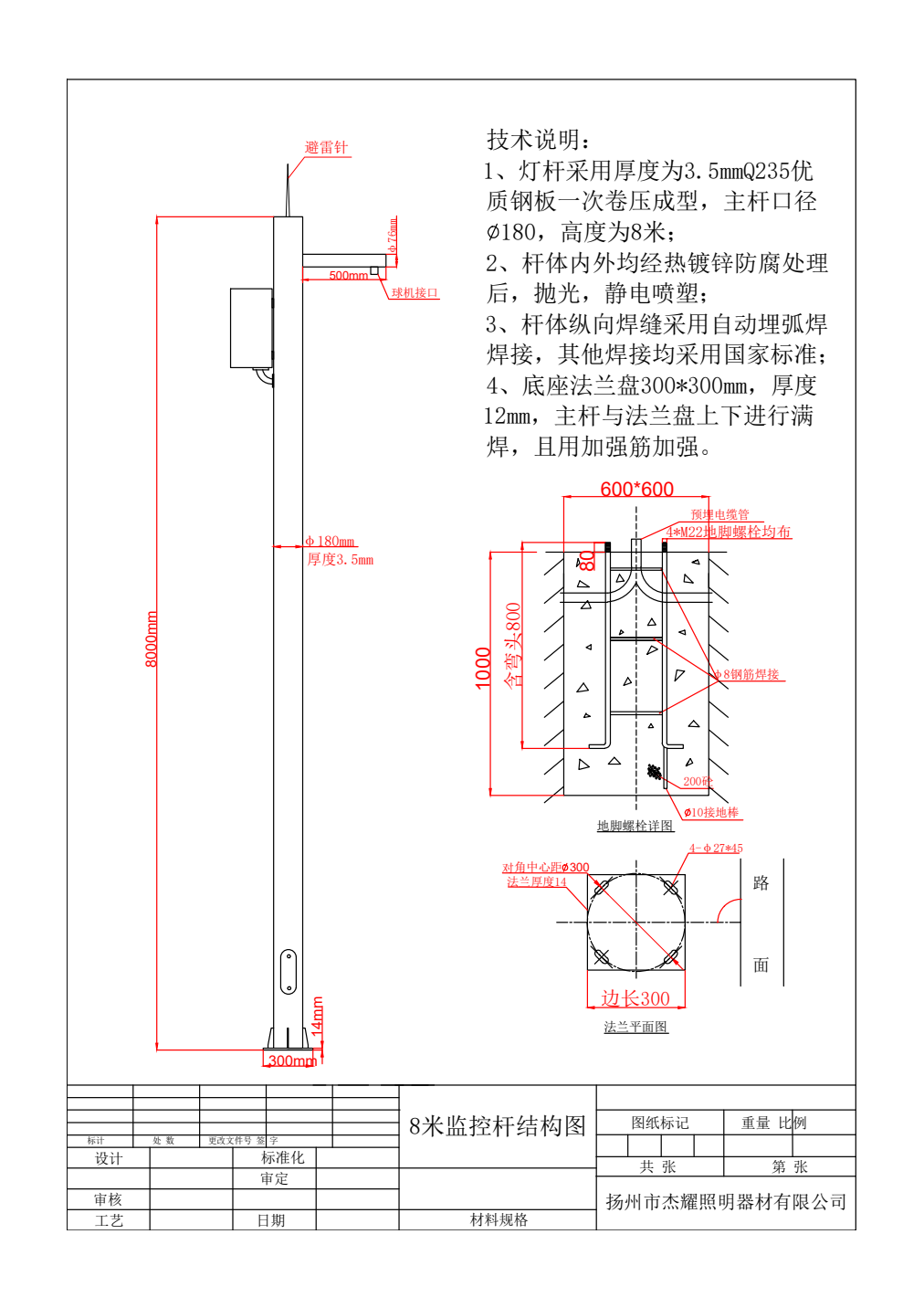
Documented 8 m reference configuration. Connection dimensions follow the final approved detail; see the plate-thickness note below.
A pan-tilt-zoom camera needs a mechanical adapter that matches its actual mounting interface. The 76 mm end detail shown on the reference arm is a steelwork dimension, not a universal camera thread or an assurance that every PTZ model fits directly.
Provide the camera and adapter drawings, fastener pattern, equipment mass and cable connector envelope. Set the camera position and viewing direction before the arm is released for manufacture. Keep enough space to remove the adapter and access its connections.
Choose the shaft height from the monitoring layout. Eight metres describes the main shaft; the exact lens height also depends on the arm level, adapter and camera body. Record those dimensions on the assembly elevation.
Product configuration and drawing data
Component Drawing reference Selection detail Main shaft 8,000 mm height; 180 mm diameter; 3.5 mm wall Fixed, round-shaft arrangement shown in the Jieyao reference. Steel Q235 stated in the notes Match the supplied material identity to the accepted order. Equipment arm 500 mm reach; 76 mm end detail Confirm adapter, direction and camera attachment. Protective finish Internal/external hot-dip galvanizing, polishing and electrostatic spray finish Colour, finish acceptance and repair scope are order selections. Base footprint 300 × 300 mm shown Use the issued plate and anchor detail for manufacture. Fixing openings Four slots marked 27 × 45 mm Confirm the complete pattern and orientation. Anchor reference Four M22 bolts shown Bolt material, thread, projection and supplied accessories require the order detail. Cable access Base access door and cable entry shown Coordinate cable sizes, connectors, segregation and service clearance. Connection detail to resolve: the archived drawing contains different base-plate thickness callouts in its notes and plan view. Plate thickness is therefore excluded from this reference schedule; the accepted connection drawing must resolve it before fabrication. The foundation sketch is not a site-independent foundation design.
Choose the equipment arrangement
Single PTZ side arm
Use the short arm to place a dome camera away from the shaft. Specify its orientation and removable adapter. This is the arrangement represented by the eight-metre drawing.
Camera plus equipment cabinet
Add a separately sized cabinet support when the project needs local power, communications or termination equipment. Cabinet dimensions, mass and door clearance become part of the equipment schedule.
Long traffic crossarm
Lane-monitoring cameras may need a much longer outreach and multiple device positions. That requires its own arm, connection and load review; it is not a length substitution for this 500 mm arm.
Cabinet supports and internal cabling
The drawing provides a pole access opening. A side cabinet, if required, is specified separately by outline, mass, attachment points and door direction. Locate it where the electrical and surveillance contractors can service it without obstructing the camera view or access cover.
Show cable entry and exit positions on the assembly drawing. Check connector passage as well as cable diameter; a cable that fits inside the shaft may still have a plug that cannot pass a small outlet. Coordinate bend space and any protective sleeves at cut edges.
Identify the electrical hand-off point in the quotation. A cabinet bracket is steelwork; it does not establish an enclosure IP rating, power rating, PoE capacity or network function.
Camera movement, equipment loads and site selection
The system designer should define any camera movement or alignment criterion needed for the intended view, lens and operating conditions. Nominal pole height and wall thickness do not by themselves establish image stability.
Include the arm, camera, adapter, cabinet, antennas and any future attachments in the agreed equipment schedule. Their masses, projected areas, positions and offsets must be reviewed with the site design basis and the foundation interface. A solar panel changes that arrangement and is not an automatic accessory to this model.
For a different monitoring position, compare the five-metre pole with panel and equipment-box supports. Its shaft, mounting levels and base geometry are a different documented configuration.
Manufacturing checks for the selected assembly
Review shaft dimensions, access opening, arm direction, adapter fit and base orientation against the approved drawing. The drawing notes specify longitudinal automatic submerged-arc welding and a galvanized, finished surface. Inspection records should identify the actual assembly and agreed acceptance criteria.
Material and geometry
Identify the steel material and wall schedule. Measure shaft length and section, then check arm reach and the equipment interfaces.
Welds and connections
Agree weld inspection method and coverage. Check the access opening, arm welds, base connection and fasteners against the released detail.
Finish and release
Record the specified visual and coating checks. Mark loose adapters and supports so the packing list matches each pole position.
Jieyao enterprise standard Q/321084 JYZM001—2023 describes material, dimensional, weld and coating inspection. The standard defines criteria; order-specific records establish what was inspected. No camera vibration result, universal wind rating or completed installation is inferred from this drawing.
Roadside video surveillance application
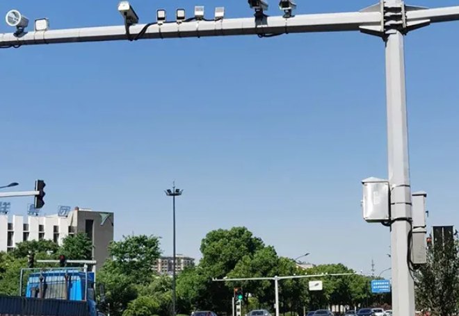
Traffic-camera application context with a different arm arrangement.
For roads, entrances and perimeter monitoring, define the viewing area before placing the pole. Check obstructions, vehicle clearance, maintenance access and the path to power or network equipment.
The photographs are mounting and application references, separate from the documented eight-metre model. A multi-camera traffic crossarm has different geometry and does not establish the capacity of the short-arm pole.
What the quotation should identify
Request the main shaft, side arm, access cover, base plate and named fixing accessories as a coordinated package. Identify camera adapters, cabinet supports, anchors and finish as specific line items. Cameras, cabinets, wiring, network equipment, foundation works and installation are included only where the quotation names them.
Send quantity, destination, camera data, required viewing position, site criteria and connection information. For an existing foundation, provide measured anchor positions, orientation and condition information. Release the resolved plate/anchor drawing before steelwork or civil installation.
Request an 8 m Camera Pole Quotation8 m camera pole questions
Is a PTZ camera included?
The page defines a steel support. Camera and electrical equipment are separate unless named in the quotation.
Does the 76 mm detail fit every camera?
No. Provide the adapter and camera interface drawings, fastening pattern and connector clearance.
Is this a hinged or lowering camera pole?
No. The reference is fixed. A hinge or lowering device requires a separately coordinated assembly and operating method.
Can a cabinet or solar panel be added?
A cabinet support can be specified with its outline and mass. A panel requires its own support geometry and review of the complete load schedule.
Which base-plate thickness should be ordered?
Resolve the conflicting archived callouts on the approved connection drawing. This page intentionally does not select a thickness or a generic foundation size.
Other camera-pole names and configurations
This is an eight-metre PTZ support configuration within the CCTV, camera and security camera pole family. Use the family page for general surveillance poles and the differences between fixed supports, lighting combinations and other mounting arrangements.
-
-