

 English
 Español
 Bahasa Indonesia

- Product details
-
JIEYAO · DRAWING-CONFIGURED CAMERA POLE
5m CCTV Camera Pole with Solar Panel and Equipment Box Supports
A five-metre steel support arrangement with a camera arm, solar-panel support and side equipment-box position. Use the documented geometry below to request a coordinated pole-and-bracket package for surveillance equipment.
This is an archived Jieyao design reference, supported by its drawing and supply record. The current order defines the released steelwork and interfaces. Cameras, solar modules, batteries and controls are included only when named in the quotation.
Request This 5 m Pole Arrangement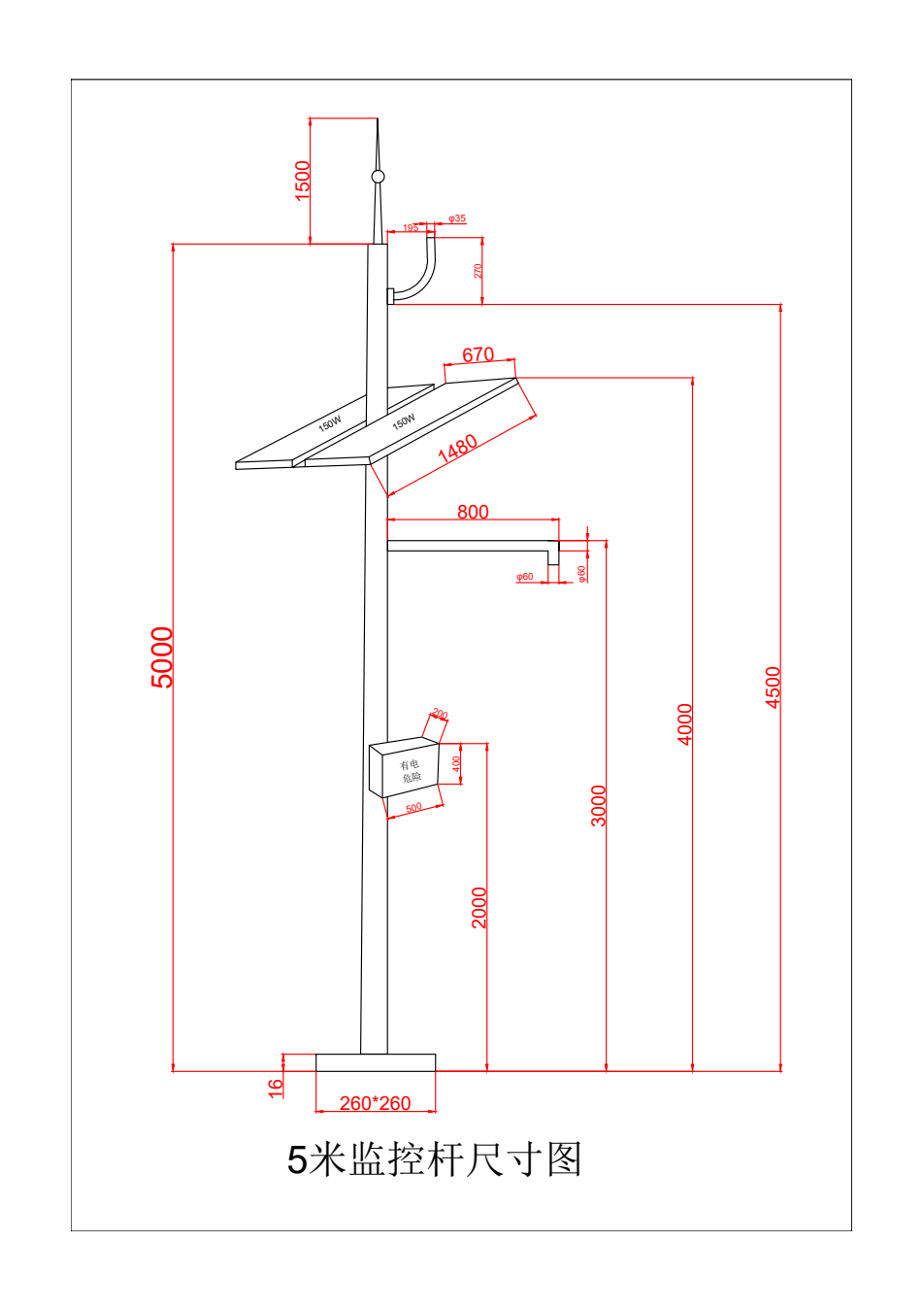
5 m reference arrangement: shaft, equipment positions and base plate.
Main shaft5,000 mm reference heightCamera arm800 mm reach · 3,000 mm levelBase plate260 × 260 × 16 mmBox outline500 × 400 × 200 mm shownCONFIGURATION DETAILS
A layout with separate camera, panel and box positions
The reference drawing separates the camera arm, panel support, upper auxiliary bracket and equipment box along the shaft. This allows the mounting interfaces to be discussed independently. It does not prescribe the camera model, communications method or energy performance.
The 5,000 mm dimension is the main pole height. A terminal element extends another 1,500 mm above it. The camera arm is at the 3,000 mm level, so a five-metre shaft should not be described as a five-metre camera mounting position.
Camera mounting
An 800 mm outreach arm is shown with a Ø60 mm end detail. Confirm whether the camera attaches directly or through an adapter, and state the required viewing direction.
Panel support
The support is shown at the 4,000 mm level. Provide the actual module geometry, fixing pattern, mass and projected area with the equipment data.
Equipment box
A 500 × 400 × 200 mm box outline is shown at the 2,000 mm reference level. Specify its enclosure, attachment and cable paths separately from the components inside it.
PRODUCT DATA
Drawing and supply-reference dimensions
Part Reference value Meaning for the order Main pole 5,000 mm Shaft height; separate from camera level and the terminal above it. Shaft diameters 100 mm top / 160 mm bottom Archived supply schedule; final drawing confirms the profile. Shaft wall At least 3 mm in the archived schedule Historical specification, not a current stock measurement. Base plate 260 × 260 × 16 mm Hole pattern and anchors require their own released detail. Camera arm 800 mm reach; Ø60 mm end At the 3,000 mm level shown. Panel-support level 4,000 mm Confirm module position and orientation. Module outline 1,480 × 670 mm shown Outline reference, not a current module SKU or tested output. Upper auxiliary bracket Ø35 mm; 195 mm horizontal and 270 mm vertical detail Identify the intended equipment before manufacture. Upper bracket level 4,500 mm shown Include any fitted item in the complete load schedule. Box outline 500 × 400 × 200 mm At the 2,000 mm reference level; no IP rating established. Air-terminal extension 1,500 mm above the shaft Mechanical provision, not lightning-system performance evidence. The drawing and supply record establish an archived configuration from 2016. The current order uses an approved drawing and equipment schedule. Original contract pages, commercial terms and customer information are not product downloads.
Read the installation heights correctly
Three different height references matter in this layout: the main shaft, the camera arm and the extension above the shaft. Specify the required camera lens position from the monitoring task and confirm its relation to the ground, pole foundation and surrounding structures.
The drawing places the equipment box below the arm and the panel support above it. Changing those positions affects cable lengths, working access and the distribution of mounted equipment. A change to camera height should therefore appear on the revised assembly drawing, rather than be treated as a site adjustment to the bracket.
Show the complete outline on the site elevation. Include nearby fences, trees, roof edges, overhead services and the intended access route for installation. Identify the foundation level used for the pole dimensions.
Define the pole package separately from electrical equipment
Specify the shaft, plate, access cover, arm, panel-support steelwork, box supports and named fasteners. List any enclosure, terminal hardware or anchor set separately so the quotation identifies the complete scope.
Item Pole-and-bracket quotation System interface Shaft and arms Geometry and steel connections Camera positions and equipment layout. Panel support Brackets and specified fasteners Modules, orientation, weight and projected area. Box mounting Support and enclosure if included Internal components, cables, heat management and protection. Camera/networking Mounting provisions unless equipment is listed Devices, field of view, network and commissioning. Battery/controller Locations and supports if specified Electrical sizing and documented performance. Base/anchors Named hardware and interface drawing Foundation design and civil installation. The 150 W labels on the archived module outlines are design labels. They are not measured outputs and do not establish energy yield, operating duration or nights of autonomy. This page defines the steel support configuration.
Match the steelwork to the actual equipment
Equipment geometry
Provide camera and module drawings, fixing points, weights and projected areas. Include cabinets, antennas and additional devices instead of leaving them as unspecified allowances.
Site design basis
State location, exposure and governing project requirements. The foundation designer needs the accepted pole reactions and actual connection details.
Maintenance method
Show how cameras, modules and boxes can be reached and removed. This drawing is a fixed-pole arrangement; it does not establish a ground-level lowering mechanism.
A module with the same wattage can have a different size or fixing pattern. A replacement camera can change bracket clearance and mounting weight. Keep the accepted equipment schedule tied to the fabrication drawing so those differences are reviewed before production.
MANUFACTURING DETAIL
Steel fabrication and connection inspection
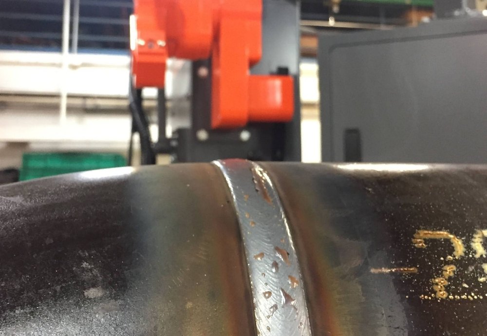
Steel weld detail.
The drawing should identify shaft sections, arm attachments, support positions, access opening and base connection. Inspection compares the manufactured parts with that drawing and the agreed material and finish criteria.
A weld photograph shows a fabrication detail; it does not establish a weld classification or NDT result. Specify the required method, coverage and acceptance basis for the order.
During fit-up, review arm direction, bracket positions, box access and cable entries. Identify loose components by pole mark and provide the agreed assembly information with them.
Pole sections, finish and delivery
The reference photograph shows pole sections with flanges and access openings during fabrication. It illustrates steelwork requiring dimensional and finish inspection, without identifying the pictured parts as this archived five-metre design.
The archived order describes galvanizing followed by passivation. Specify the current protective system, appearance, acceptance criteria and any colour requirement in the quotation. A finish statement from another product is not a measured result for this configuration.
Protect interfaces during packing and keep arms, support parts and fixing sets identifiable. Include the drawing revision, packing list and agreed inspection records with delivery.
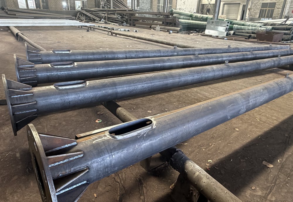
Pole sections before finishing.
Base plate and civil-work interface
The reference plate measures 260 × 260 × 16 mm. Those three dimensions do not define an anchor pattern, bolt capacity or foundation size. Request the released plate-hole layout and anchor detail for the selected pole assembly.
The pole supplier and civil designer should agree responsibility for reactions, anchors, template, fixing projection, conduits and earthing. Where anchors are supplied with the steelwork, list their dimensions, materials, nuts and washers in the package. Where anchors are supplied locally, issue the accepted interface drawing before construction.
Application context: outdoor camera positions
A yard, access route or perimeter installation needs a clear camera view and a practical service position. The layout determines camera direction and mounting level while preserving access to the cabinet and cable entries.
Use the dimensioned reference above for the five-metre product enquiry. Send a site plan and device schedule when requesting a variation.
For other arrangements, compare the CCTV camera pole family. A solar street-light pole carrying a luminaire has a different equipment layout.
Enquiry checklist
Enquire About the 5 m CCTV PoleReference and quantity
Identify this five-metre arrangement, quantity and destination. Mark changes to height, reach, bracket levels or box dimensions.
Equipment and scope
Send camera, module, enclosure and auxiliary-device drawings. State which equipment and fasteners each party supplies.
Design and records
Provide site criteria, supporting-structure information, finish requirements and inspection documents. Identify any witnessing scope.
5 m CCTV pole questions
Is the camera mounted at five metres?
The main shaft is five metres; the camera arm is shown at the three-metre level. State the required camera position if it differs.
Does five metres include the upper terminal?
The drawing shows a separate 1,500 mm extension above the shaft. Confirm the final overall clearance and terminal arrangement.
Is a complete solar CCTV system included?
The page defines steelwork and mounting interfaces. Cameras, modules, batteries, controllers and networking are included only when named in the quotation.
Can the equipment-box size change?
Provide its outline, mounting, weight and cable entries. Review the support and complete assembly for the changed enclosure.
Are module power labels performance guarantees?
No. They are archived design labels. Energy performance requires the selected electrical components and a site calculation.
Is this a folding or tilting pole?
The reference is fixed. A lowering arrangement requires a separate coordinated design and operating method.
-
-