

 English
 Español
 Bahasa Indonesia

- Product details
-
JIEYAO · RAIL YARD LIGHTING SUPPORTS
Rail Yard High Mast Lighting Poles
Steel lighting poles and high masts for rail sidings, locomotive service areas and intermodal yards. Configure the shaft, floodlight head, base connection and maintenance access around the working track layout. The package can cover the steel support alone or a coordinated lighting assembly, as itemised in the quotation.
Send the yard plan and equipment schedule so the pole positions, mounting arrangement and delivery scope can be reviewed together. This range is for area illumination; it is separate from overhead contact-line supports and railway signalling equipment.
Request a Rail Yard Pole Configuration
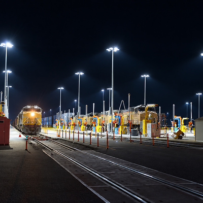
Rail-yard application photograph from the supplied reference collection. It illustrates the operating setting, not an identified Jieyao installation.
Select the support arrangement
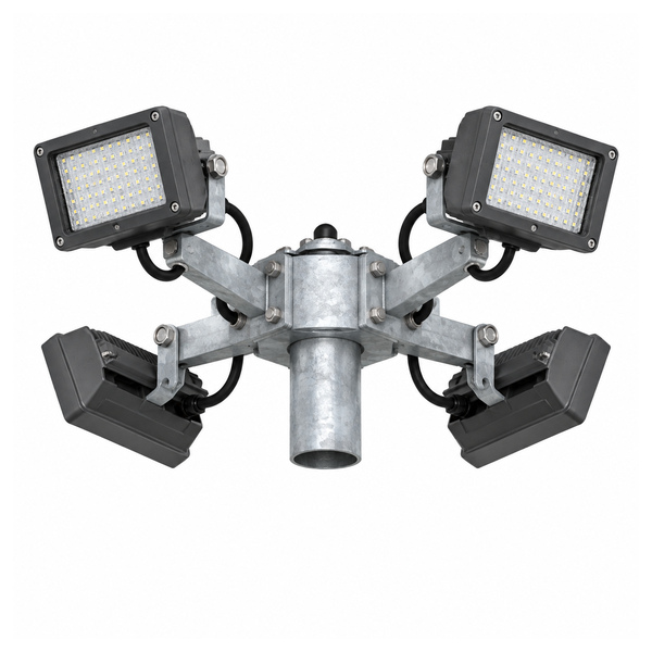
Radial floodlight head
An outward-facing head provides several aiming directions from one support location. Select the bracket positions and exact luminaires against the yard lighting model.
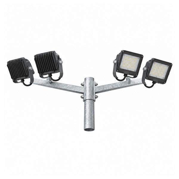
Opposing crossarms
Two head directions can serve working areas on opposite sides of the support. Review shadows from parked rolling stock and the view along the tracks.
Lowering-ring mast
A coordinated lowering arrangement brings the light ring to a service position. Include the drive, suspension, locking arrangement, controls and maintenance envelope in the selected package.
Pictured head configurations

Radial head configuration reference. The pictured fixture count describes the image; it is not a certified load rating or a lighting layout for every yard.
The luminaire mounting pattern determines how the equipment sits on the pole, while the optic and aiming angle determine where its light goes. Compare both before choosing the shaft height. A head selected from appearance alone can leave the work area beside a train in shadow.
Specify each fixture model, mass, projected area and bracket footprint. Identify whether drivers, junction boxes and other accessories are mounted on the head or elsewhere. These details form the top-load schedule for the support design.

Opposing-head configuration reference, showing the connection direction and separate aiming brackets. Final dimensions follow the order drawing.
What belongs in a rail-yard quotation
Swipe horizontally to read all columns on a small screen.
Assembly Configuration data Supply boundary Steel shaft Height, section form, material, segment lengths and joints Pole mark and released structural drawing Lighting head Fixed crossarm, radial head or lowering ring; mounting positions and orientation Headframe and brackets listed separately from luminaires Luminaires Model, quantity, input power, optics, driver location, mass and projected area Only included where named in the quotation Base connection Base plate, anchor pattern, level, orientation and conduit interface Anchor package and civil works separately identified Maintenance equipment Working position, service access and any lowering-system components Access method coordinated with the operator Finish Galvanizing and any specified compatible coating system Surface preparation, inspection and repair requirements Electrical items Cable interfaces, junctions, earthing connections and controls Incoming supply and site wiring responsibilities agreed Coordinate the pole with the railway operating layout
Trackside working space
Locate the support against the operator’s approved clearances and the space needed for walking, inspection and vehicle movement. Keep the access door and maintenance position usable.
Rolling-stock shadows
Evaluate lighting with representative wagons or locomotives in place. A clear-track calculation alone may not show the shadows that occur during normal service.
Signals and viewpoints
Include driver viewpoints, nearby signals, neighbours and other sensitive directions in the lighting brief. Review aiming and shielding with the relevant railway team.
Electrified locations need coordination with overhead equipment and the project electrical design. The lighting support does not replace contact-line engineering, railway clearance approval or the site earthing and bonding design.
Height, fixture count and power are selected together
A taller support changes the installation geometry, access plan and structural demand. More floodlights add mass and projected area as well as light output. Choose the arrangement from the working areas and an exact photometric file, then check the complete support.
For a useful proposal, define the measurement planes and the maintained lighting criteria for each task area. Separate trackside walkways, coupling or inspection positions, service aprons and vehicle routes where the operator requires different treatment. Confirm uniformity, glare and spill-light criteria alongside the illumination target.
There is no single wattage-per-metre or luminaire-count-per-pole rule on this page. The quotation schedule should identify the actual fixtures and the calculation conditions used for the selected layout.
Manufacturing evidence and order inspection

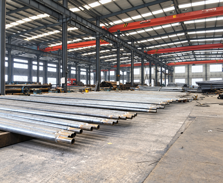
Workshop photograph from the supplied manufacturing collection. It shows pole preparation and handling, not a completed rail-yard project or an installation-specific test.
The manufacturing file should connect the pole mark to its material records, drawing revision, dimensional inspection and protective finish. Check the shaft joints, head interface, access opening and base orientation before packing.
Jieyao’s factory inspection file No. (2026) 219 provides one historical 15 m floodlight-pole manufacturing example. It records two sampled poles from a batch of two, inspected on 1 July 2026. Selected measured dimensions are shown below to illustrate traceable inspection evidence.
Swipe horizontally to read all columns on a small screen.
Item in the historical file Recorded result Scope Pole height 15 m Named 15 m floodlight-pole samples Top diameter 120.5 mm / 120.2 mm Two recorded sample readings Bottom diameter 281 mm / 280.5 mm Two recorded sample readings Base-plate thickness 25.2 mm / 25.2 mm Sampled base plates Powder-coating readings 81 μm / 82 μm Powder layer; not zinc thickness These measurements document the identified historical samples. They do not establish a rail-yard rating, a standard foundation or the dimensions of every offered mast. The rail-yard order requires its own approved configuration and inspection schedule. This manufacturer inspection record is separate from third-party certification.
Delivery and maintenance access
Identify mast segments, head assemblies, fasteners and loose electrical or mechanical items on the packing list. Agree transport lengths, unloading arrangements and the site assembly sequence before dispatch. Protect the finish and keep matching parts marked.
For a lowering-ring arrangement, show the ring’s service position and the area needed to operate it. For a fixed head, agree the means of reaching the luminaires without treating the track as an unrestricted work area. Maintenance access and any required railway work permissions belong in the site plan.
For an existing yard, provide the measured base connection and current pole information before requesting a replacement. A similar height or an apparently matching bolt count does not establish compatibility.
Related products and technical guides
For a complete maintenance mechanism, see the raising and lowering high mast system. For the structural supply format, compare high mast shafts and lighting assemblies.
The wind-load and fixture EPA guide explains the structural inputs, while the aiming and glare commissioning checklist supports the lighting review.
Rail yard lighting pole questions
Is this the same product as an overhead line pole?
No. This page covers area-lighting supports. Contact-line support and railway signalling have different functions and approval requirements.
Can the support be supplied without floodlights?
Identify a pole-only or pole-and-head scope in the enquiry. The quotation lists the luminaires and other equipment only where included.
Is the illustrated head suitable for any rail yard?
The pictures show configuration directions. Select the equipment, bracket geometry and support design for the specific yard plan and loads.
Do the 15 m inspection readings certify a taller mast?
No. They concern the identified historical samples. Another pole configuration needs its own drawing and applicable inspection records.
What is needed to start a quotation?
Send the yard layout, quantity, destination, proposed support positions, equipment schedule, lighting criteria, wind/design basis, ground information and maintenance constraints.
Request the configured supply package
Tell us whether the enquiry concerns a new yard, an extension or replacement supports. Include drawings and the required handover documents so the proposed steelwork, lighting head and site interfaces can be itemised clearly.
Request a Rail Yard Pole Configuration -
-