

 English
 Español
 Bahasa Indonesia

- Product details
-
Product focus: Replacement steel light-pole shafts with a specified hot-dip galvanized and compatible topcoat finish. Match the new shaft, base and retained arm interfaces to a measured replacement schedule. Reuse of an existing foundation requires its own structural assessment.
Replacement shafts for an existing lighting installation
A replacement order starts with the existing interfaces: anchor pattern, base level, cable route, arm connection and equipment load. This page addresses a new shaft made around those recorded interfaces, with a specified duplex protection system. The existing coastal-road pole page remains the broader product destination for new coastal installations.
The supplied item can be a shaft with base plate and access door, a shaft with new arm connections, or a coordinated shaft-and-arm replacement. Luminaires, retained anchors and foundations should be listed separately. A product photograph showing a similar base is not proof that it will fit the installed anchors.
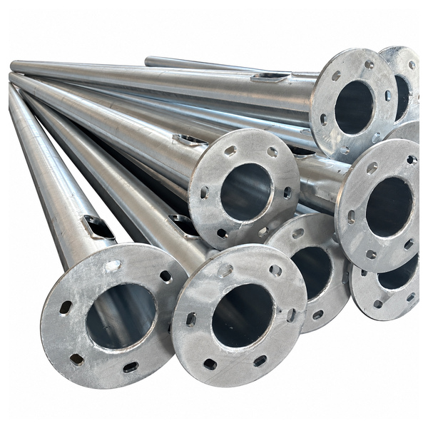 Replacement-shaft product direction. Each order uses a defined shaft section and measured base interface.
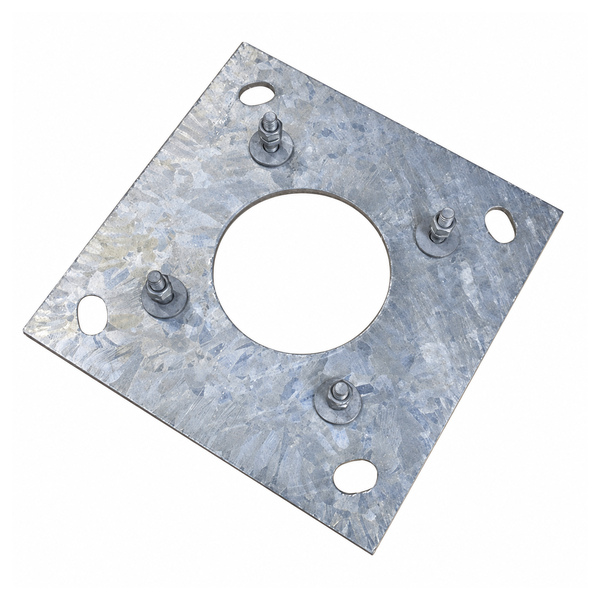 Base-plate reference. Plate size, hole pattern and anchor condition must be checked independently.
Existing-base interface schedule
Interface Record from site / approved documents New-shaft confirmation Anchor layout Number, centres or pitch circle, orientation and measured deviations Released base plate and hole geometry Anchor details Thread, exposed length, nuts, washers and condition Compatible connection and approved fastener arrangement Base level Finished level, grout and drainage condition Seating and cable-entry arrangement Cable route Position, diameter, usable slack and earthing connection New opening position and access requirements Arm connection Sleeve / socket geometry, fixing holes and orientation Matched interface drawing Luminaire and accessories Actual mass, wind area and mounting position Updated structural equipment schedule Measure the installed anchor pattern in both directions and record its orientation relative to the road. A nominal pitch-circle value alone can hide a rotated pattern, bent anchors or an installation that differs from the old drawing. Where the condition or geometry cannot be established, do not treat a matching base plate as approval to reuse the foundation.
The existing foundation assessment should address the changed shaft and equipment loads as well as the condition of concrete and anchors. Corrosion, impact damage, cracking or inadequate exposed threads can prevent reuse even when the hole centres appear correct. That assessment belongs to the project design and site inspection; the replacement shaft quotation does not certify the old foundation.
12 m shaft drawing: a real interface reference
A Jieyao single-arm drawing dated 21 October 2026 records a 12 m shaft and detachable arm connection. The following values identify that drawing. They show the level of dimensional information required for a replacement order, rather than a universal replacement model or an approval for an existing coastal foundation.
Drawing feature Recorded dimension Boundary Shaft height 12,000 mm Overall elevation shown Shaft wall 5 mm Drawing value, not a sample thickness reading Base plate 400 × 400 × 20 mm Square plate in this drawing Anchor openings Four 25 × 45 mm slots Does not establish the thread or condition of installed anchors Arm outreach 1,500 mm shown to luminaire interface Check retained arm and luminaire geometry separately Arm connection detail 200 mm dimension shown at detachable joint Use the complete joint detail, not the length alone Luminaire label 150 W modular LED Label does not define fixture mass or wind area This source drawing does not identify a duplex coating test for that exact assembly. The replacement finish is specified and inspected as part of the new order. Do not transfer a corrosion-test result from another pole to this shaft simply because both are galvanized steel.
For a replacement schedule, add the measured site anchor plan to the proposed shaft elevation. Mark the access-door direction, arm direction and cable opening on the same orientation reference. This allows the supplier and site designer to compare the new assembly with the installation it is replacing before fabrication begins.
Duplex protection: zinc layer and compatible topcoat
A duplex finish combines hot-dip galvanizing with a compatible paint or powder-coating system. The protective layers need a defined preparation and application process; a colour selection alone is not a coating specification. Agree the zinc requirement, surface preparation after galvanizing, topcoat type, colour, thickness acceptance and repair system for the actual exposure.
Jieyao enterprise steel-road-pole standard Q/321084 JYZM002—2023 states zinc-layer requirements of at least 65 μm for metal below 5 mm and at least 86 μm for metal at or above 5 mm. These are requirements in the stated standard, not readings from the 12 m reference drawing. The purchase specification establishes the applicable standard and acceptance basis for the new shafts.
Finish control Specify before manufacture Inspection evidence Steel preparation Edges, weld cleanup, drainage and venting details Fabrication inspection before galvanizing Zinc protection Applicable standard and required coating measurement basis Zinc readings and surface observations Topcoat compatibility Preparation method and compatible coating system Application / preparation record as agreed Colour and appearance Approved colour, texture and visible-surface acceptance Visual comparison to approved reference Topcoat thickness Product-system requirement and measurement method Identified measurement results Damage repair Accepted repair material and procedure for each layer Repair record for any accepted damaged area 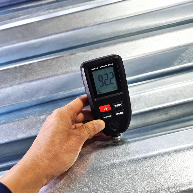 Coating inspection context. The displayed photograph is not presented as an order-specific zinc or topcoat reading.
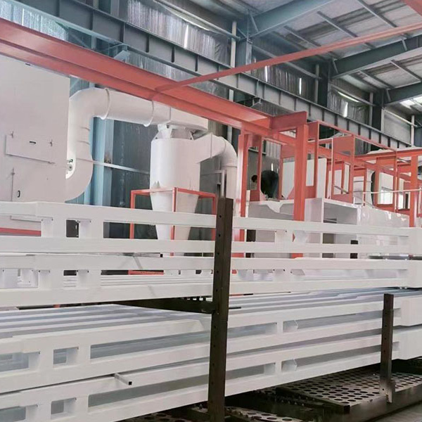 Finish-production reference. Confirm the selected coating system and colour against the order documents.
Structural details that must follow the new equipment
A replacement luminaire may use less electrical power but have a larger projected area or a different bracket mass. Those mechanical properties influence the shaft, arm and base design. Supply the actual equipment data rather than assuming the previous pole design remains adequate because the new lamp has a lower wattage label.
Retained arms need a condition check and a dimensioned connection. Socket diameter, insertion length, fixing pattern and corrosion condition all matter. If the connection differs, the new shaft can be reviewed with a new matching arm assembly; an improvised adapter or extra drilled holes should not be treated as an accepted replacement detail.
Access-door position also affects the replacement installation. The opening must remain usable after the shaft is oriented to its arm and anchor pattern. Compare the new door and internal cable route with available cable length, electrical terminations and maintenance access. An otherwise correct pole can be impractical if its door faces an obstruction.
Fabrication and replacement-order inspection
Stage Product detail to check Traceable record Drawing release Measured existing interface and new shaft revision Approved interface and assembly drawings Material and forming Grade, plate thickness, profile and taper Material identification and dimensions Welded assembly Seam, base plate, stiffeners and arm attachments Visual checks and specified weld examinations Fit and orientation Hole pattern, door direction and arm connection Dimensional inspection against released drawing Protective finish Zinc and topcoat checks kept separate Coating inspection and accepted repair record Dispatch Pole marks, matching arms, loose parts and finish protection Packing list and handling instructions The enterprise standard describes factory inspections, but an order-specific record is still needed to show what was checked on the supplied replacement. Identify the inspected pole marks or sampling basis. If a gauge reading is supplied, the record should state the layer and method; total coating thickness cannot automatically be treated as zinc thickness.
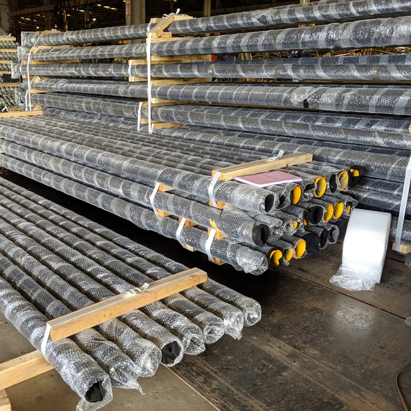 Packed-shaft reference. Keep the replacement location and pole mark traceable through packing and site delivery.
Protect the finish at supports and contact points during packing and unloading. Preserve pole marks so the shaft intended for a particular anchor pattern is delivered to the correct location. Where several existing bases differ, group them by verified interface drawing instead of assuming that every pole in the road uses the same base.
Send the site survey, old drawing if available, photographs, retained arm and luminaire data, proposed finish, quantity by pole mark and destination. The return quotation should identify new and retained components separately. This keeps the replacement shaft order distinct from a new-foundation pole order and avoids counting unverified reuse as a supplied product feature.
Frequently asked questions
Will a new base plate make an old foundation reusable?
No. A geometric match does not establish anchor or foundation capacity and condition. The responsible project team must assess reuse for the new assembly.
Can I order just the coated shaft?
A shaft-only scope can be defined, with its base, door and retained-equipment interfaces specified. New arms, anchors and luminaires are separate counted items.
Is the 12 m drawing a standard retrofit size?
No. It is one documented geometry reference. The actual replacement must match its measured site interface and approved new design.
Does duplex coating guarantee a fixed service life?
No fixed life is established here. Exposure, coating system, detailing, damage and maintenance affect service performance.
Can a retained arm be fitted to the new shaft?
Only after checking its condition, connection geometry and equipment loads. Identify it on the released assembly drawing.
What inspection evidence should come with replacement shafts?
Ask for the agreed material, dimensional, weld and coating records tied to the supplied pole marks, plus the released drawings and packing list.
Related products and enquiry
Send the current drawing, equipment schedule, quantity and destination through Contact Jieyao for a configuration-specific quotation.
-
-